


Unit 3: Electric Circuits
3.1: Electric Circuits
Circuit Quantities
Voltage: It is the difference in electric potential between two points in a circuit. It is measured in volts (V) and is represented by the symbol "V".
It is the driving force that causes current to flow in a circuit.
Current: It is the flow of electric charge through a circuit. It is measured in amperes (A) and is represented by the symbol "I". It is the rate at which charge flows through a circuit.
Resistance: It is the opposition to the flow of electric current in a circuit. It is measured in ohms (Ω) and is represented by the symbol "R". It is determined by the material and dimensions of the conductor.
Power: It is the rate at which energy is transferred in a circuit. It is measured in watts (W) and is represented by the symbol "P". Power is calculated by multiplying voltage and current.
Frequency: It is the number of cycles per second in an alternating current (AC) circuit. It is measured in hertz (Hz) and is represented by the symbol "f". It determines the speed at which the AC signal alternates.
Impedance: It is the total opposition to the flow of electric current in a circuit. It is measured in ohms (Ω) and is represented by the symbol "Z". It is a combination of resistance, capacitance, and inductance.
Current
Current: It is the flow of electric charge through a conductor.
Direct current (DC): Current flows in one direction only.
Alternating current (AC): Current changes direction periodically.
Current is measured in amperes (A).
Factors affecting current:
Resistance: Higher resistance leads to lower current.
Voltage: Higher voltage leads to higher current.
Temperature: Higher temperature leads to higher resistance, which in turn leads to lower current.
Applications of current:
Electric power generation: Current is used to generate electricity in power plants.
Electronics: Current is used in electronic devices such as computers, televisions, and smartphones.
Transportation: Current is used to power electric vehicles and trains.
Medical devices: Current is used in medical devices such as pacemakers and defibrillators.
Ohm's Law
Ohm's Law is a fundamental law in electrical circuits that describes the relationship between voltage, current, and resistance.
It states that the current through a conductor between two points is directly proportional to the voltage across the two points, and inversely proportional to the resistance between them.
Ohm's Law can be mathematically expressed as:
V = I * Rwhere
V is the voltage across the conductor
I is the current flowing through the conductor
R is the resistance of the conductor.
Ohm's Law is used extensively in electrical engineering to design and analyze circuits.
It is used to calculate the voltage, current, or resistance of a circuit component, given the values of the other two quantities.
For example, if we know the voltage and resistance of a circuit, we can use Ohm's Law to calculate the current flowing through the circuit.
If we know the current and resistance, we can calculate the voltage across the circuit.
It is important to note that Ohm's Law is only applicable to linear circuits, where the resistance remains constant with changes in voltage or current.
In non-linear circuits, the relationship between voltage, current, and resistance is more complex and cannot be described by a simple formula.
Resistance
Resistance: It is the opposition that a material or a circuit offers to the flow of electric current.
It is measured in ohms (Ω).
Factors affecting resistance
Length: The longer the wire, the greater the resistance.
Cross-sectional area: The greater the cross-sectional area, the lower the resistance.
Temperature: The higher the temperature, the greater the resistance.
Material: Different materials have different resistivities, which affect resistance.
Types of resistors
Fixed resistors: These have a fixed resistance value and cannot be changed.
Variable resistors: These have a variable resistance value and can be adjusted.
Thermistors: These have a resistance that varies with temperature.
Light-dependent resistors: These have a resistance that varies with light intensity.
Applications of resistance
Resistors are used in electronic circuits to control the flow of current and voltage.
They are used in sensors to measure temperature, light, and other physical quantities.
They are used in heating elements to convert electrical energy into heat.
They are used in electric motors to control the speed and torque.
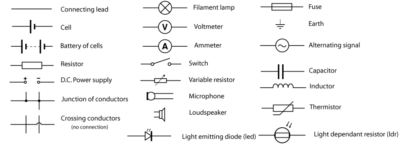
Circuit Symbols
Circuit Measuring Tools
Circuit measuring tools are used to measure various electrical parameters in a circuit.
These tools are essential for troubleshooting, testing, and designing circuits.
Multimeter: A versatile tool that can measure voltage, current, and resistance. It is used to troubleshoot circuits and check the continuity of wires and components. Multimeters come in both analog and digital versions.
Oscilloscope: Used to measure and display voltage signals over time. It is used to analyze waveforms and diagnose problems in circuits. Oscilloscopes come in both analog and digital versions.
Function generator: Used to generate various types of waveforms such as sine, square, and triangle waves. It is used to test circuits and simulate different types of signals.
Logic analyzer: Used to capture and analyze digital signals in a circuit. It is used to troubleshoot digital circuits and analyze the behavior of digital signals.
Power supply: Used to provide a constant voltage or current to a circuit. It is used to test circuits and power electronic devices.
LCR meter: Used to measure the inductance, capacitance, and resistance of a circuit. It is used to test and design circuits that use inductors, capacitors, and resistors.
Series Circuit
Series circuit: It is a circuit in which the components are connected in a single loop, so the current flows through each component in turn.
The components in a series circuit have the same current flowing through them.
The total resistance of a series circuit is equal to the sum of the individual resistances.
The voltage across each component in a series circuit is proportional to its resistance.
Parallel Circuit
Parallel circuit: It is a circuit in which the components are connected in separate branches, so the current divides between them.
The components in a parallel circuit have the same voltage across them.
The total resistance of a parallel circuit is less than the smallest individual resistance.
The current through each branch of a parallel circuit is proportional to the inverse of its resistance.
3.2: Power in a Circuit
Power is the rate at which energy is transferred or converted. In an electric circuit, power is the rate at which electrical energy is transferred from a power source to a device or load.
The formula for power in a circuit is:
P = VIwhere P is power, V is voltage, and I is current.
The unit of power is the watt (W). One watt is equal to one joule per second (J/s). Other units of power include kilowatts (kW) and megawatts (MW).
Calculating Power
To calculate power in a circuit, you need to know the voltage and current. Once you have these values, you can use the formula:
P = VIFor example, if a circuit has a voltage of 12 volts and a current of 2 amps, the power would be:
P = 12V x 2A = 24W
Power and Resistance
Power in a circuit is also related to resistance. The formula for power can be rewritten as:
P = I^2Ror
P = V^2/Rwhere R is resistance.
This shows that as resistance increases, power decreases. This is because more energy is lost as heat in the circuit due to the resistance.
3.3: Steady State Circuits
Kirchhoff's Voltage Law
Kirchhoff's Voltage Law (KVL) is a fundamental law in electrical engineering that states that the sum of all voltages around a closed loop in a circuit must be zero. This law is based on the principle of conservation of energy, which states that energy cannot be created or destroyed, only transferred from one form to another.
"The algebraic sum of all voltages around any closed loop in a circuit is equal to zero."
KVL is used to analyze and solve circuits that contain multiple voltage sources and resistors.
By applying KVL to a closed loop in a circuit, we can determine the voltage drop across each resistor and the voltage of each source.
KVL assumes that the circuit is a closed loop and that there are no changing magnetic fields within the loop.
In reality, circuits may contain changing magnetic fields, which can induce voltages that violate KVL.
In such cases, we need to use more advanced techniques, such as Kirchhoff's Current Law and Faraday's Law of Induction, to analyze the circuit.
Example of KVL
Consider the following circuit:
     +-----R1-----+

     |             |

    V1             R3

     |             |

     +-----R2-----+
Applying KVL to the loop formed by R1, R2, and R3, we get:
V1 - V(R1) - V(R2) - V(R3) = 0where V(R1), V(R2), and V(R3) are the voltage drops across resistors R1, R2, and R3, respectively.
Kirchhoff's Current Law
Kirchhoff's Current Law (KCL) is a fundamental law in electrical engineering that states that the total current entering a node or junction in a circuit must be equal to the total current leaving that node or junction.
In other words, the algebraic sum of all the currents entering and leaving a node must be zero.
KCL is based on the principle of conservation of charge, which states that charge cannot be created or destroyed, only transferred from one point to another.
KCL is applicable to both DC and AC circuits.
KCL is used to analyze and solve complex circuits by breaking them down into smaller parts and applying the law to each node or junction.
KCL can be expressed mathematically as: Σi(in) = Σi(out), where Σi(in) is the sum of all currents entering the node and Σi(out) is the sum of all currents leaving the node.
KCL is often used in conjunction with Kirchhoff's Voltage Law (KVL) to solve circuits.
Consider a simple circuit with three resistors connected in parallel to a voltage source. The current flowing through each resistor can be determined using KCL as follows:
At the junction where the resistors are connected, the total current entering the junction is equal to the total current leaving the junction.
Let's assume that the current flowing through the first resistor is I1, the current flowing through the second resistor is I2, and the current flowing through the third resistor is I3.
Applying KCL to the junction, we get: I1 + I2 + I3 = I_total
Since the resistors are connected in parallel, the voltage across each resistor is the same and can be calculated using Ohm's Law.
The total current flowing through the circuit can be calculated by summing the currents flowing through each resistor: I_total = I1 + I2 + I3.
Resistors in Series
When resistors are connected in series, they are connected end-to-end, so that the current flows through one resistor and then through the other.
The total resistance of the circuit is the sum of the individual resistances.
The formula for calculating the total resistance of resistors in series is:
R_total = R1 + R2 + R3 + ... + Rnwhere R1, R2, R3, ..., Rn are the individual resistances.
The current flowing through each resistor in a series circuit is the same, but the voltage across each resistor is different. The voltage across each resistor is proportional to its resistance.
Resistors in Parallel
When resistors are connected in parallel, they are connected across each other, so that the current flows through each resistor.
The total resistance of the circuit is less than the resistance of the smallest resistor.
The formula for calculating the total resistance of resistors in parallel is:
1/R_total = 1/R1 + 1/R2 + 1/R3 + ... + 1/Rnwhere R1, R2, R3, ..., Rn are the individual resistances.
The voltage across each resistor in a parallel circuit is the same, but the current flowing through each resistor is different.
The current flowing through each resistor is proportional to its conductance.
Non-Ideal Batteries
Real batteries are non-ideal and have internal resistance.
The internal resistance of a battery causes a voltage drop across the battery when a current flows through it.
The voltage across the terminals of a battery is less than its EMF due to this voltage drop.
The voltage drop across the internal resistance of a battery can be calculated using Ohm's law: V = IR, where V is the voltage drop, I is the current flowing through the battery, and R is the internal resistance of the battery.
Electromotive Force
EMF stands for electromotive force and is the voltage generated by a battery or other source of electrical energy.
EMF Equation
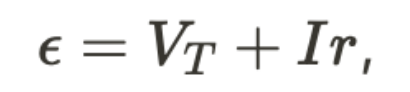
where r is the internal resistance of the battery.
The EMF of a battery is the maximum voltage that it can provide when no current is flowing through it.
The EMF of a battery is affected by factors such as temperature, the concentration of the electrolyte, and the materials used in the electrodes.
The EMF of a battery can be measured using a voltmeter connected across its terminals when no current is flowing through it.
3.4: Capacitors in a Circuit
Capacitors in Series
When capacitors are connected in series, the total capacitance is less than the capacitance of any individual capacitor. The formula for calculating the total capacitance of capacitors in series is:
1/C_total = 1/C_1 + 1/C_2 + ... + 1/C_nwhere
C_total is the total capacitance
C_1, C_2, ..., C_n are the capacitances of individual capacitors.
The voltage across each capacitor in series is proportional to its capacitance. The capacitor with the smallest capacitance will have the highest voltage across it.
Capacitors in Parallel
When capacitors are connected in parallel, the total capacitance is the sum of the capacitances of individual capacitors. The formula for calculating the total capacitance of capacitors in parallel is:
C_total = C_1 + C_2 + ... + C_nwhere:
**C_**total is the total capacitance
C_1, C_2, ..., C_n are the capacitances of individual capacitors.
The voltage across each capacitor in parallel is the same. The charge on each capacitor is proportional to its capacitance.
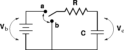
RC Circuits
RC circuits are circuits that contain a resistor and a capacitor. These circuits are used in a variety of applications, including filters, timing circuits, and oscillators.
Capacitor Charging
When a capacitor is connected to a voltage source through a resistor, it charges up to the voltage of the source.
The time it takes for the capacitor to charge up to 63.2% of the source voltage is given by the time constant, which is equal to the product of the resistance and the capacitance.

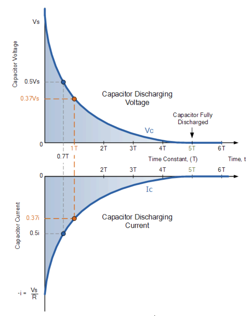
Capacitor Discharging
When a charged capacitor is disconnected from a voltage source and connected to a resistor, it discharges through the resistor.
The time it takes for the capacitor to discharge to 36.8% of its initial voltage is given by the time constant.
RC Filters
RC circuits can be used as filters to pass or block certain frequencies. A high-pass filter passes high frequencies and blocks low frequencies, while a low-pass filter passes low frequencies and blocks high frequencies. The cutoff frequency is the frequency at which the filter begins to attenuate the signal.
RC Oscillators
RC circuits can also be used as oscillators, which generate a periodic waveform. The frequency of the waveform is determined by the values of the resistor and capacitor in the circuit.