


Unit 5: Electromagnetism
5.1: Electromagnetism
Electromagnetic Induction
Electromagnetic induction: It is the process of generating an electromotive force (EMF) or voltage across a conductor by exposing it to a changing magnetic field. This phenomenon was discovered by Michael Faraday in 1831.
Electromagnetic induction has numerous practical applications, including:
Generators and alternators: These devices use electromagnetic induction to convert mechanical energy into electrical energy.
Transformers: These devices use electromagnetic induction to transfer electrical energy from one circuit to another.
Induction heating: This process uses electromagnetic induction to heat a metal object by inducing eddy currents within it.
Magnetic levitation: This technology uses electromagnetic induction to levitate an object above a magnetic surface.
Magnetic Flux
Magnetic flux: It is the measure of the strength of a magnetic field passing through a given area. It is denoted by the symbol Φ and is measured in Weber (Wb) or Tesla meter squared (Tm²).
The formula for magnetic flux is:
Φ = B * A * cos(θ)where:
Φ is the magnetic flux
B is the magnetic field strength
A is the area of the surface
θ is the angle between the magnetic field and the surface normal
The SI unit of magnetic flux is Weber (Wb) or Tesla meter squared (Tm²). One Weber is equal to one Tesla meter squared.
Magnetic flux is used in various applications such as:
Electric generators
Transformers
Inductors
Magnetic sensors
Magnetic levitation systems
Faraday's Law
Faraday's Law of Electromagnetic Induction states that a changing magnetic field induces an electromotive force (EMF) in a conductor. This law was discovered by Michael Faraday in 1831.
This law is expressed mathematically as:
EMF = -dΦ/dtwhere EMF is the electromotive force, Φ is the magnetic flux, and t is time.
The negative sign indicates that the induced EMF opposes the change in magnetic flux.
The unit of EMF is volts (V).
The unit of magnetic flux is webers (Wb).
The unit of time is seconds (s).
Key Concepts
A magnetic field is created by a moving electric charge.
A changing magnetic field induces an EMF in a conductor.
The induced EMF creates an electric current in the conductor.
The magnitude of the induced EMF is proportional to the rate of change of the magnetic field.
The direction of the induced EMF is such that it opposes the change in the magnetic field that produced it. This is known as Lenz's Law.
Faraday's Law has numerous applications in modern technology, including:
Generators: Electrical generators use Faraday's Law to convert mechanical energy into electrical energy.
Transformers: Transformers use Faraday's Law to transfer electrical energy from one circuit to another.
Induction cooktops: Induction cooktops use Faraday's Law to heat up cooking vessels.
Magnetic levitation: Magnetic levitation trains use Faraday's Law to levitate above the tracks.
Faraday's Law has some limitations, including:
The conductor must be in motion relative to the magnetic field to induce an EMF.
The conductor must be part of a closed circuit for an electric current to flow.
The induced EMF is proportional to the rate of change of the magnetic field, so a steady magnetic field will not induce an EMF.
Lenz's Law
Lenz's Law is a fundamental law of electromagnetism that describes the direction of the induced electromotive force (EMF) and current that is generated in a conductor when it is exposed to a changing magnetic field.
The law states that the direction of the induced EMF and current is such that it opposes the change that produced it.
The formula for Lenz's law is given by:
ε = -dΦ/dtwhere
ε is the induced EMF
Φ is the magnetic flux
t is time.
The negative sign indicates that the induced EMF is in the opposite direction to the change in magnetic flux.
This means that when a magnetic field is applied to a conductor, the induced current will flow in a direction that creates a magnetic field that opposes the original magnetic field.
Lenz's Law is based on the principle of conservation of energy, which states that energy cannot be created or destroyed, only transformed from one form to another.
The law has many practical applications, including in the design of electric generators and motors, transformers, and in the braking systems of trains and other vehicles.
Lenz's Law is also used in the study of electromagnetic waves and the behavior of charged particles in magnetic fields.
The law was first formulated by the Russian physicist Heinrich Lenz in 1834, and it is one of the basic laws of electromagnetism.
5.2: Inductance
Inductance is a property of an electrical circuit that opposes changes in current. It is measured in henries (H) and is represented by the symbol L.
Inductance is created when a current flows through a conductor, generating a magnetic field around it.
This magnetic field stores energy, which opposes any changes in the current that created it.
When the current changes, the magnetic field changes as well, and the energy stored in the field is released, creating a voltage that opposes the change in current.
Inductance is used in a variety of electrical devices, including transformers, motors, and generators. It is also used in electronic filters to block certain frequencies of signals.
Calculation of Inductance
The inductance of a circuit can be calculated using the formula:
L = NΦ/IWhere
L is the inductance in henries
N is the number of turns in the coil
Φ is the magnetic flux through the coil
I is the current flowing through the coil
Energy Stored in an Inductor
An inductor is a passive electronic component that stores energy in a magnetic field when an electric current flows through it. The energy stored in an inductor can be calculated using the following formula:
W = 1/2 * L * I^2Where
W is the energy stored in joules
L is the inductance of the inductor in henries
I is the current flowing through the inductor in amperes.
The energy stored in an inductor is proportional to the square of the current flowing through it. This means that the energy stored in an inductor can be increased by increasing the current flowing through it.
When the current flowing through an inductor is interrupted, the magnetic field collapses and the energy stored in the inductor is released. This can cause a voltage spike, which can damage electronic components if not properly controlled.
Inductors are commonly used in electronic circuits to filter out unwanted signals, store energy, and regulate voltage. Understanding the energy stored in an inductor is important for designing and analyzing electronic circuits.
LR Circuit Behavior
An LR circuit is a circuit that consists of a resistor (R) and an inductor (L) connected in series. When a voltage is applied to the circuit, the current that flows through the circuit changes over time due to the inductor's behavior.
When a voltage is applied to an LR circuit, the current initially increases, but the inductor resists the change in current flow.
As a result, the current eventually reaches a steady state value.
The time it takes for the current to reach the steady state value is determined by the time constant of the circuit, which is equal to the inductance divided by the resistance.
When the voltage is removed from the circuit, the inductor releases the energy stored in its magnetic field, which causes the current to continue to flow for a short period of time. This is known as the inductor's back EMF (electromotive force).
LR circuits are commonly used in electronic devices such as power supplies, filters, and oscillators. They are also used in electric motors and generators to control the flow of current and generate magnetic fields.
LC Circuit Behavior
An LC circuit is a type of resonant circuit consisting of an inductor (L) and a capacitor (C) connected together.
When an LC circuit is charged, the capacitor stores energy in the form of an electric field, while the inductor stores energy in the form of a magnetic field.
The energy oscillates back and forth between the capacitor and the inductor, resulting in a resonant frequency.
The resonant frequency of an LC circuit is given by the formula:
f = 1 / (2π√LC)where f is the resonant frequency, L is the inductance of the inductor, and C is the capacitance of the capacitor.
At the resonant frequency, the impedance of the circuit is at a minimum, and the current is at a maximum.
When an LC circuit is first charged, the capacitor begins to store energy in the form of an electric field.
As the capacitor charges, the current in the circuit increases, causing the magnetic field in the inductor to increase.
When the capacitor is fully charged, the current in the circuit reaches its maximum value, and the magnetic field in the inductor is at its maximum.
As the capacitor begins to discharge, the current in the circuit decreases, causing the magnetic field in the inductor to decrease.
When the capacitor is fully discharged, the current in the circuit reaches zero, and the magnetic field in the inductor is at its minimum.
The energy stored in the magnetic field is then transferred back to the capacitor, and the cycle repeats.
LC circuits are used in a variety of applications, including:
Radio tuning circuits
Oscillators
Filters
Voltage regulators
In radio tuning circuits, LC circuits are used to select a specific frequency from a range of frequencies. In oscillators, LC circuits are used to generate a stable frequency.
In filters, LC circuits are used to pass or block certain frequencies. In voltage regulators, LC circuits are used to smooth out fluctuations in voltage.
5.3: Maxwell’s Equations
Maxwell's equations are a set of four fundamental equations that describe the behavior of electric and magnetic fields.
These equations were developed by James Clerk Maxwell in the 19th century and are considered one of the most important contributions to the field of electromagnetism.
Gauss's Law for Electric Fields
This equation states that the electric flux through any closed surface is proportional to the charge enclosed within the surface. In mathematical terms, it can be written as:
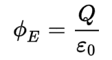
where
Φ is electric flux through a closed surface S enclosing any volume V
Q is total charge enclosed within V
ε0 is electric constant
Gauss's Law for Magnetic Fields
This equation states that the magnetic flux through any closed surface is zero. In mathematical terms, it can be written as:
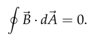
There are no magnetic charges. Magnetic field lines always close in themselves.
Faraday's Law of Electromagnetic Induction
This equation states that a changing magnetic field induces an electric field. In mathematical terms, it can be written as:
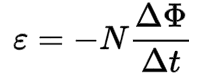
where
ε is induced voltage
N is number of loops
Δ ϕ is change in magnetic flux
Δ t is change in time
Ampere's Law with Maxwell's Correction
This equation relates the magnetic field to the current density and the rate of change of the electric field. In mathematical terms, it can be written as: