Physics
AP Physics C: Electricity and Magnetism
Unit 4: Magnetic Fields
Solenoids
Ampère's Law
Biot-Savart Law
Magnetic Fields
Magnetic Field Produced by a Current-Carrying Wire
Force Between Two Parallel Current-Carrying Wires
Forces on a Wire in an External Magnetic Field
Magnetic & Electric Field Interactions
Right Hand Rule
Right Hand Rule
12th

Unit 4: Magnetic Fields
4.1: Magnetic Fields
Magnetic fields: These are created by moving electric charges.
They are represented by lines of force that show the direction of the magnetic field.
The strength of the magnetic field is measured in tesla (T).
The magnetic field of a straight conductor can be determined using the right-hand rule.
If the right-hand thumb points in the direction of the current, the fingers will curl in the direction of the magnetic field.
The magnetic field of a circular conductor can be determined using the right-hand rule.
If the right-hand thumb points in the direction of the current, the fingers will curl in the direction of the magnetic field inside the loop.
Outside the loop, the magnetic field points in the opposite direction.
A solenoid is a coil of wire that produces a magnetic field when an electric current is passed through it.
The magnetic field inside a solenoid is uniform and parallel to the axis of the coil.
The strength of the magnetic field can be increased by increasing the number of turns in the coil or by increasing the current.
A bar magnet has two poles, a north pole and a south pole.
The magnetic field lines of a bar magnet extend from the north pole to the south pole.
The strength of the magnetic field is strongest at the poles and decreases as you move away from the magnet.
Right Hand Rule for Magnetic Fields
The right hand rule is a mnemonic technique used to determine the direction of a magnetic field in relation to the direction of the current flowing through a wire.
It is based on the principle that a magnetic field is created around a current-carrying wire.
How to use the right hand rule
Hold your right hand so that your thumb points in the direction of the current flow.
Curl your fingers around the wire in the direction of the magnetic field.
Your fingers will point in the direction of the magnetic field lines.
The right hand rule is used in various applications, including:
Determining the direction of the magnetic field around a current-carrying wire.
Determining the direction of the force on a current-carrying wire in a magnetic field.
Determining the direction of the force on a charged particle moving in a magnetic field.
Magnetic & Electric Field Interactions
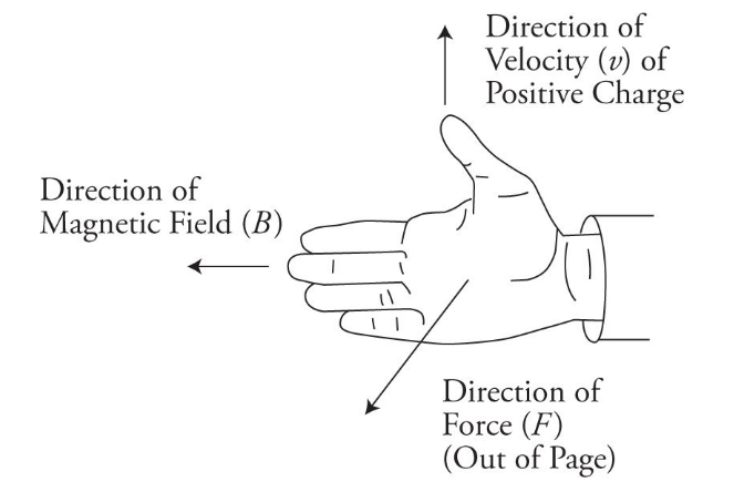
When a charged particle moves through a magnetic field, it experiences a force perpendicular to both the direction of motion and the magnetic field.
This is known as the Lorentz force and can be calculated using the equation:
F = q(v x B)where
F is the force
q is the charge of the particle
v is the velocity of the particle
B is the magnetic field.
Similarly, when a charged particle is placed in an electric field, it experiences a force in the direction of the electric field. This force can be calculated using the equation:
F = qEwhere
F is the force
q is the charge of the particle
E is the electric field.
When both magnetic and electric fields are present, the particle experiences a combined force that is the vector sum of the two individual forces. This can be calculated using the equation:
F = qE + q(v x B)
The interaction between magnetic and electric fields is important in many areas of physics, including particle accelerators, plasma physics, and astrophysics. It is also the basis for many technological applications, such as magnetic resonance imaging (MRI) and particle detectors.
4.2: Current-Carrying Wires & Magnetic Field
Forces on a Wire in an External Magnetic Field
When a wire carrying current is placed in an external magnetic field, it experiences a force. This force is known as the Lorentz force and is given by the equation:
F = I L x Bwhere
F is the force
I is the current in the wire
L is the length of the wire in the magnetic field
B is the magnetic field strength.
The direction of the force is given by the right-hand rule. If the thumb of the right hand points in the direction of the current, and the fingers point in the direction of the magnetic field, then the palm of the hand will point in the direction of the force.
If the wire is not perpendicular to the magnetic field, then only the component of the magnetic field perpendicular to the wire will cause a force. This component is given by:
B_perp = B sin(theta)where theta is the angle between the wire and the magnetic field.
If the wire is part of a closed loop, then the forces on each segment of the wire will cancel out, except for the segments at the ends of the loop. These segments will experience a net force and will move in a circular path. This is the principle behind the electric motor.
Torque on a Wire
When a wire is twisted, a torque is applied to it. This torque is proportional to the force applied and the distance from the axis of rotation. The torque can be calculated using the formula:
T = F * r * sin(theta)where
T is the torque
F is the force applied
r is the distance from the axis of rotation,
theta is the angle between the force and the radius vector.
The direction of the torque is perpendicular to both the force and the radius vector, and follows the right-hand rule. If the fingers of the right hand are curled in the direction of the force, and the thumb points in the direction of the radius vector, then the direction of the torque is given by the direction in which the thumb points.
The torque on a wire can be used to measure the torsional stiffness of the wire. By measuring the angle of twist and the applied torque, the torsional stiffness can be calculated using the formula:
k = T / thetawhere
k is the torsional stiffness
theta is the angle of twist.
The torsional stiffness of a wire depends on its material properties, such as its modulus of elasticity and its cross-sectional area. It also depends on the length and diameter of the wire, as well as the method of twisting.
Magnetic Fields From a Current Carrying Wire
When an electric current flows through a wire, it generates a magnetic field around the wire. This magnetic field can be visualized using magnetic field lines, which show the direction and strength of the magnetic field at different points around the wire.
The direction of the magnetic field around a current-carrying wire can be determined using the right-hand rule. If you point your right thumb in the direction of the current flow, the direction of the magnetic field lines can be determined by the direction your fingers curl around the wire.
The strength of the magnetic field around a current-carrying wire depends on the amount of current flowing through the wire and the distance from the wire. The magnetic field strength decreases as the distance from the wire increases.
A solenoid is a coil of wire that is wrapped around a cylindrical object, such as a metal rod. When a current flows through the wire, it generates a magnetic field that is concentrated inside the coil. The strength of the magnetic field can be increased by increasing the number of turns in the coil or by increasing the current flowing through the wire.
Magnetic Field Produced by a Current-Carrying Wire
A current-carrying wire produces a magnetic field around it.
The direction of the magnetic field can be determined using the right-hand rule.
If the thumb of the right hand points in the direction of the current, the fingers curl in the direction of the magnetic field.
Force Between Two Parallel Current-Carrying Wires
When two parallel wires carrying current in the same direction are placed close to each other, they experience a force of attraction.
This is because the magnetic fields produced by the currents in the wires are in the same direction and interact with each other.
When two parallel wires carrying current in opposite directions are placed close to each other, they experience a force of repulsion.
This is because the magnetic fields produced by the currents in the wires are in opposite directions and interact with each other.
The force between the wires can be calculated using the formula:
F = μ₀I₁I₂L / 2πdwhere
F is the force
μ₀ is the permeability of free space
I₁ and I₂ are the currents in the wires
L is the length of the wires
d is the distance between the wires.
Drawing Magnetic Fields
Direction of the field: Magnetic field lines always point from the north pole of a magnet to the south pole. In the case of a current-carrying wire, the direction of the magnetic field can be determined using the right-hand rule.
Strength of the field: The strength of the magnetic field is indicated by the density of the field lines. The closer together the lines are, the stronger the field.
Shape of the field: The shape of the magnetic field depends on the shape of the magnet or current-carrying wire. For example, the field around a straight wire is circular, while the field around a loop of wire is more complex.
Magnetic field inside vs. outside: In general, magnetic fields are stronger closer to the source (i.e. the magnet or wire) and weaker further away. However, the exact shape of the field can vary depending on the geometry of the source.
Interactions with other fields: Magnetic fields can interact with electric fields and with other magnetic fields. These interactions can lead to complex patterns of field lines and can be used to create a wide range of devices, from electric motors to MRI machines.
4.3: Biot–Savart Law and Ampère’s Law
Biot-Savart Law
The Biot-Savart Law is a fundamental law in electromagnetism that describes the magnetic field produced by a current-carrying wire. It was discovered by Jean-Baptiste Biot and Felix Savart in 1820.
The Biot-Savart Law states that the magnetic field at a point is proportional to the current density and the distance from the point to the current element. The direction of the magnetic field is perpendicular to both the current element and the vector from the current element to the point.
Mathematically, it is written as:
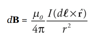
where
B is magnetic field intensity
μ₀ is permeability of free space
N is number of turns
I is current intensity
R is radius
The Biot-Savart Law is used to calculate the magnetic field produced by a current-carrying wire or a group of wires. It is also used in the calculation of the magnetic field of a solenoid, a toroid, and other complex geometries.
The Biot-Savart Law is only valid for steady currents and does not take into account the effects of changing electric fields. It also assumes that the current density is constant throughout the wire, which may not be the case in practice.
Biot-Savart Law Sample Problem
A long straight wire carries a current of 5 A. Find the magnetic field at a point 3 cm away from the wire.
Solution
The formula for the magnetic field due to a current-carrying wire is given by:
B = (μ₀ * I)/(2πr)where
Bis the magnetic field,Iis the current,ris the distance from the wire, andμ₀is the permeability of free space.
Substituting the given values in the formula, we get:
B = (4π * 10^-7 * 5)/(2π * 0.03)B = 3.33 * 10^-5 T
Therefore, the magnetic field at a point 3 cm away from the wire carrying a current of 5 A is
3.33 * 10^-5 T.
Ampère's Law
Ampère's Law is a fundamental law of electromagnetism that relates the magnetic field around a closed loop to the electric current passing through the loop. The law was discovered by André-Marie Ampère in 1826.
The law states that the line integral of the magnetic field around a closed loop is equal to the current passing through the loop multiplied by a constant known as the permeability of free space.
Mathematically, the law can be expressed as:
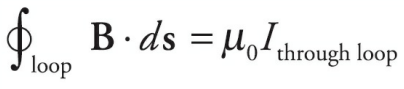
where
B is the magnetic field
dl is an infinitesimal element of the loop
μ₀ is the permeability of free space
I is the current passing through the loop.
Ampère's Law Sample Problem
A long, straight wire carries a current of 10 A. What is the magnetic field at a distance of 5 cm from the wire?
Solution
We can use Ampère's Law to solve this problem. Ampère's Law states that the line integral of the magnetic field around a closed loop is equal to the current passing through the loop multiplied by the permeability of free space.
We can choose a circular loop of radius 5 cm around the wire. The magnetic field at every point on the loop is parallel to the tangent at that point. Therefore, the line integral of the magnetic field around the loop is simply the product of the magnetic field and the circumference of the loop.
The current passing through the loop is equal to the current in the wire, which is 10 A.
Therefore, we have:
B * 2πr = μ0 * Iwhere B is the magnetic field, r is the radius of the loop, μ0 is the permeability of free space, and I is the current passing through the loop.
Substituting the given values, we get:
B * 2π(0.05) = 4π * 10^-7 * 10
B = 2 * 10^-6 T
Therefore, the magnetic field at a distance of 5 cm from the wire is 2 * 10^-6 T.