


Unit 4: Electric Circuits
Electric Current:
It comprises an energy source typically a battery, one or more conducting materials, and circuit components such as resistors and capacitors.
Current;
Continous flow of charge
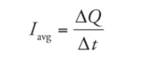
Current is the charge per unit of time expresssed in coulumb per second (ampere)
Average Current:
Battery and Voltage:
A battery is a device that maintains an electric potential difference between the two terminals.
The battery could consist of a single cell or multiple cells.
A voltage difference between two points in a conducting material causes a charge to flow.
The voltage is measured in volts.
As long as the potential difference is maintained, the flow of charge will continue.
The flow is from higher potential to lower potential. The electricity also flows in that direction called direct current.
Resistors and Resistance:
Resistance: It is the impedance to the flow of electricity through a material. As a charge moves through a material, it eventually hits a non-moving nucleus in the material.
Resistivity: It can be thought of as the density of nuclei the electrons may strike.
R = ρ l / A
This equation is applied to shapes with uniform cross-sectional areas and cannot be applied to those with varying cross-sectional areas.
Example: A wire of radius 1 mm and length 2m is made of platinum (resistivity = 1× 10⁻⁷Ω·m).
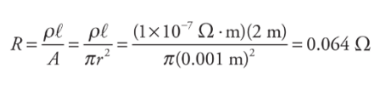
Resistance is measured in ohms (Ω)
Resistivity is measured in ohm-meters (Ωm)
Materials with:
Low resistivity: conductors
High resistivity: insulators
Combining Resistors and Equivalent Resistance:
Equivalent resistance: When two or more resistors are combined mathematically, the resulting resistance is called equivalent resistance.
In arrangements of three or more resistors, it is possible for the arrangement to be a mixture of series and parallel. It can be solved accordingly to find the equivalent resistance.
Resistors in Series:
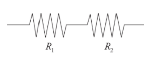
It can be thought of as a single wire of a greater length.
Resistors arranged in series result in an overall resistance that isgreater than the resistance of any individual resistors in the arrangement.
Example: A resistor having an electrical resistance value of 100 ohms, is connected to another resistor with a resistance value of 200 ohms. The two resistances are connected in series. What is the total resistance across the system?
Solution:
R1 = 100 ohm
R2 = 200 ohm
Req = R1 + R2 = 300 ohm
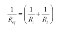
Resistors in parallel:
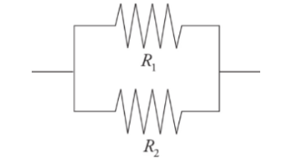
They behave like a wire with a greater cross-sectional area.
Resistors arranged in parallel result in an overall resistance that is less than any of the resistors.
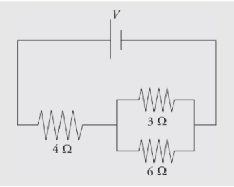
Example: Calculate the equivalent resistance for the following circuit:
 Solution:
First, you see that the three resistors are not purely in parallel or purely in series. There must be a pair which is purely in parallel or series. The current that flows through the 4Ω could flow through the 3Ω or 6Ω resistor,so none of the resistors are purely parallel. However, the no current flows through the 3Ω can flow through the 6Ω because of the junction before that combination, so those two resistors are purely parallel. You find the equivalent resistance of the two parallel resistors:
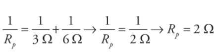
The current that flows into the 4Ω must flow into this equivalent resistor, so this resistance is in series with the 4Ω resistor. The total equivalent resistance in the circuit is R= 4Ω + 2Ω =6Ω. The reason for considering these equivalent resistances is because the easiest problem to solve is the simple, one-resistor problem presented originally. You can represent many combinations of resistors in series or parallel as a single equivalent resistor, and then use Ohm’s Law to solve for the current that flows out of the battery into the circuit.
Measuring Current and Voltage in a circuit:
Ammeter: It is a device with a very low resistance that measures the current.
Voltmeter: It measures the electric potential difference called the potential drop.
Ohm’s Law:
It shows the relationship between potential differences and current.
V = IR
R is the resistance in the circuit.
V is the potential difference in the circuit
I is the electric current
Example: If a voltage of 9 V is applied between the ends of the wire from example 1, and the wire is Ohmic, what will be the resulting current?

Power Dissipation:
The power dissipated by a circuit component is given by the product of the current through the component and the voltage drop across it.
P = VI
P = I2R
P = V2IR
P is the power
V is the potential difference in the circuit.
I is the electric current.
Example: A 9V battery is connected to a resistor having a resistance of 10Ω.What is the current and power across the resistor?
Solution:
I = V/R = 9/10 = 0.9 A
P = VI = 9 × 0.9 = 8.1 J/s or 8.1 W
Kirchhoff’s Law:
It is used when analysing the circuits.
The loop rule states that the voltage drop across any complete loop in a circuit is 0V.
This statement follows from the conservation of energy when applied to circuits.
The junction rule states that the sum of all current flowing into any junction is equal to the current flowing out of the junction.
This statement follows from the conservation of charge.
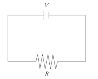
A very simple circuit:
A simple circuit consists of one battery with voltage V and one resistor of resistance R connected by wires.
EMF and Internal Resistance:
The voltage supplied by an ideal battery is referred to as EMF (electromotive force).
A battery in a circuit can be modelled as an ideal EMF in series with a resistor. In this model, r is called the internal resistance of the battery.
The voltage measured across the EMF source is called the terminal voltage.
Capacitors in the circuit:
A capacitor stores energy in an electric field.
A parallel-plate capacitor consists of two plates of area A and separation d.
Capacitance determines the amount of charge that can be stored on the plates for a given voltage
C = k ε0 A/d
Capacitance is measured in a unit called farad.
The ratio of the charge on either plate to the voltage across the plates is capacitance.
Δ V = Q/C
Combination of Capacitors and Equivalent Capacitance:
➢ Capacitors in parallel:
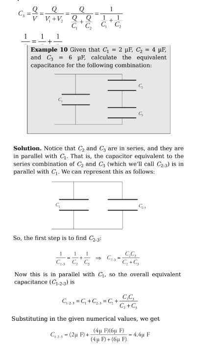
 Capacitors in series:
Charging and Discharging:
An uncharged capacitor may be charged by connecting it to a battery. After the connection is made, the uncharged capacitor has a potential difference of 0V.
A charged capacitor may be discharged by connecting the two plates to a resistor.
Altering the capacitance of a capacitor:
The capacitance is given by:
C = k ε0 A/d
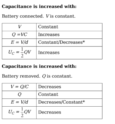
There are two scenarios for making these changes to a charged capacitor in a circuit:
The battery may remain connected, causing the potential difference to remain constant.
The battery may be disconnected, causing the charge on each plate to remain constant
RC Circuits with Capacitors in Steady State:
When a capacitor is discharged, the voltage between the plates is 0V. As a result, it acts like a wire.
The discharged capacitor short circuits any resistors arranged in parallel with the capacitor.
The situation is reversed when the capacitor is fully charged. It acts like a broken wire.
The fully charged capacitor short circuits and resistors arranged in series with the capacitor.
Example: Determine the current through and the voltage across each electrical device in the following circuit when
a) the switch has just been closed
b) the switch has been thrown for a long period of time
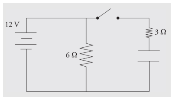
a) When the switch has just been closed, the capacitor is treated like a wire with no resistance. The circuit behaves like a simple parallel circuit. There are 12V across the 6Ω resistor, so 2 amps of current flow through it. There are 12V across the 3Ω resistor, so 4 amps flow through it. By Kirchhoff’s Law, the currents add 6 amps through the battery, and the equivalent resistance of the circuit is 2Ω.b) After the switch has been closed for a long period of time, the capacitor behaves like an infinite resistor. There are still 12V across the 6Ω resistor, so 2 amps of current will still flow through it. If the capacitor behaves like an infinite resistor, no current can flow through that branch. There will be no current through the 3Ω resistor. The capacitor will have 12V across it, and there will be no voltage across the 3Ω resistor (otherwise current would be flowing through it). The current will be 2 amps through the battery, and the equivalent resistance ofthe circuit is 6Ω.