


AP Physics 2 Ultimate Guide
Unit 1: Fluids - Pressure and Forces
Fluids
The substances that can flow. This property generally applies to liquids and gases. We can't tell that solids can flow due to their high interatomic forces of attraction.
Density
The mass per unit volume of a substance is defined as density. Density is a positive scalar quantity.
So, density at a point of a fluid is expressed as:
p= m/V
S.l unit: kg/m³
C.G.S unit: g/cc
Example: if 10-3 m3 of oil has a mass of 0.8 kg, then the density of this oil is:
Solution: p = m/v = 0.8/10^-3 = 800 kg/m³
Pressure
Pressure P is defined as the magnitude of the normal force acting per unit surface area.

S.I unit: Pascal (Pa); 1Pa = 1 N/m²
Practical units: atmospheric pressure (atm), bar, torr
1 atm = 1.01325 × 10^5 Pa = 1.01325 bar = 760 torr = 760 mm of Hg
Example: A vertical column made of cement has a base area of 0.5 m2. If its height is 2 m, and the density of cement is 3000 kg/m3, how much pressure does this column exert on the ground?
Solution: The force the column exerts on the ground is equal to its weight, mg, so we’ll find the pressure it exerts by dividing this by the base area, A. The mass of the column is equal to pV, which we calculate as follows:
m = pV =pAh = (3 × 10³ kg/m³) (0.5m²) (2m) = 3 × 10³kg
Therefore, P = F/A = mg/A = (3 × 10³kg)(10 N/kg) / 0.5m² = 6 × 10^4 Pa = 60 kPa
Hydrostatic Pressure
It is the pressure due to liquid.
It depends only on the density of the liquid and the depth below the surface.
Pliquid = force/area = Fg liquid / A = p(lwh)g /lw =pgh
Total (absolute) pressure: Ptotal = P0 + Pliquid = P0 + PGH
Ptotal = Patm + pgh
Note: the total pressure comes into account when the tank were open to the atmosphere.
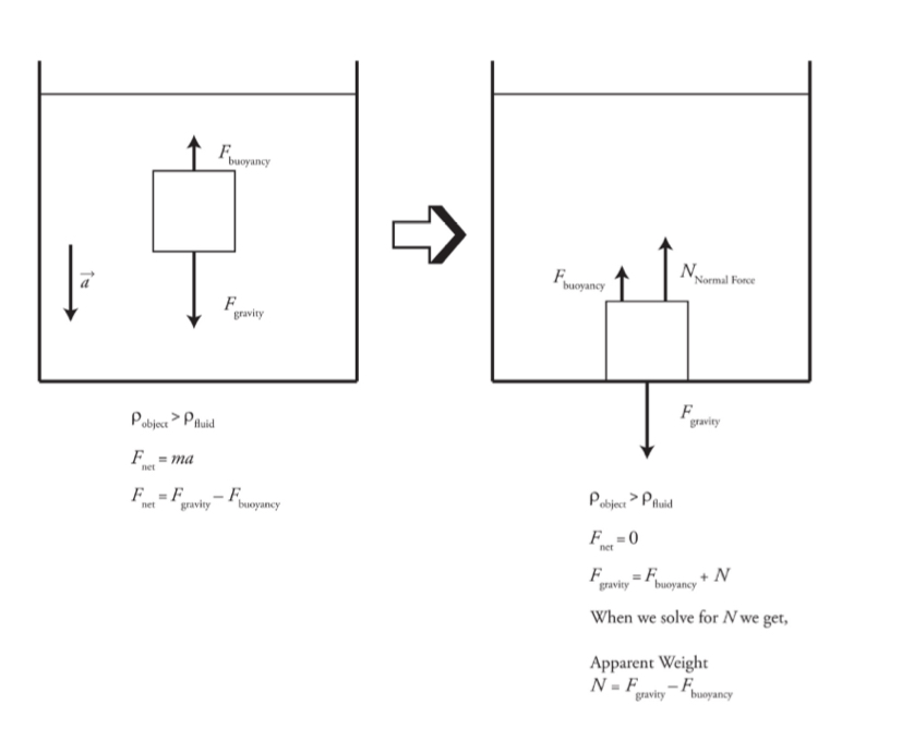
Buoyancy
If a body is fully or partially immersed in a fluid, it experiences an upward force due to the fluid called buoyant force, and the phenomenon is called buoyancy.
It uses Archimedes principle.
Buoyant force: Fbuoy= Pfluid V sub g
Vsub/ V = Pobject/Pfluid
Example: An object with a mass of 150 kg and a volume of 0.75 m3 is floating in ethyl alcohol, whose density is 800 kg/m3. What fraction of the object's volume is above the surface of the fluid?
Solution: The density of the object is Pobject = m/V = 150kg/0.75m³ = 200kg/m³
The ratio of the object density to the fluid’s density is Pobject/ Pfluid = 200kg/m³ /800kg/m³ = ¼
This means that ¼ of the object’s volume is below the surface of the fluid; therefore, the fraction above the surface is 1-(1/4) =3/4.
Make sure you know exactly what the question is asking.
Typically you can use this equation to find the volume submerged, but this question asks for the volume not submerged.
Buoyancy diagrams
Diagram showing an object floating in a liquid.

Diagram showing an object with a density greater than the fluid density as it sinks to the bottom of the tank.
The Continuity Equation: Flow Rate and Conservation of Mass
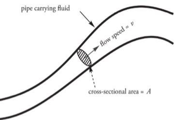
The Volume Flow Rate
It is the volume of fluid that passes through a particular point per unit of time.
volume flow rate: f = Av
S.I unit: m^3/s
The Continuity Equation:
The density of the fluid is constant.
A1V1 =A2V2
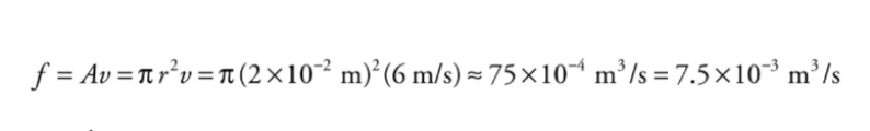
Example: A circular pipe of non-uniform diameter carries water.
At one point in the pipe, the radius is 2 cm and the flow speed is 6m/s.What is the volume flow rate?
What is the flow speed at a point where the pipe constricts to a radius of 1 cm?
Solution
At any point, the volume flow rate, f, is equal to the cross-sectional area of the pipe multiplied by the flow speed.
By the Continuity Equation, we know that the volume flow rate must be the same at all points, so the volume flow rate must be the same as in part a.

A second approach to part (b) is to use proportional reasoning. From the Continuity Equation, we know that v, the flow speed, is inversely proportional to A, the cross-sectional area of the pipe.
If the pipe radius decreases by a factor of 2 (from 2cm to 1cm), then A decreases by a factor of 4, because A is proportional to r^2.
If A decreases by a factor of four then v will increase by a factor of 4, Therefore, the flow speed at a point where the
pipe's radius is 1 cm will be 4 • (6 m/s) = 24 m/s.
Bernoulli's Equation: Conservation of Energy in Fluids
The fluid is incompressible.
The fluid's viscosity is negligible.
The fluid is streamlined.
The equation looks very similar to the conservation of energy with total mechanical energy.
An alternative is a way of stating Bernoulli's equation
P + pgy + ½ pv²

A1, A2: Cross-sectional areas at points 1 and 2
p1, p2: Pressures
v1, v2 : Velocities
h1, h2, : Elevations
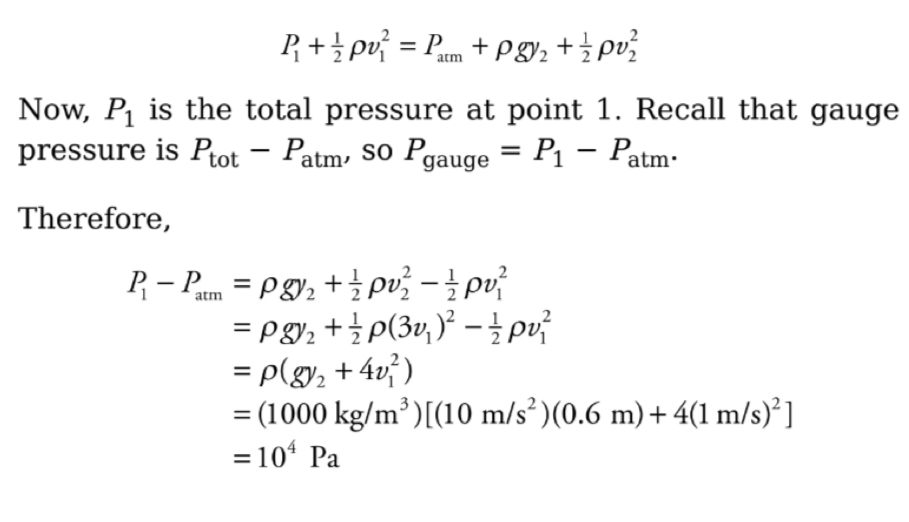
Example: In the figure below, a pump forces water at a constant flow rate through a pipe whose cross-sectional area, A, gradually decreases: at the exit point, A has decreased to ⅓
its value at the beginning of the pipe. If y = 60 cm and the flow speed of the water just after it leaves the pump (Point 1 in the figure) is 1m/s, what is the gauge pressure at Point 1?
Solution: We will apply Bernoullis equation to point 1 and the exit point, point 2. We will choose the level of point 1 as the horizontal reference level; this makes y1 = 0. Now, because the cross-sectional area of the pipe decreases by a factor of 3 between points 1 and 2, the flow speed must increase by a factor of 3, that is v2= 3V1. Since the pressure at 2 is Patm Bernoulli’s equation becomes:
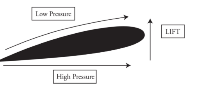
Bernoulli's Effect
At comparable heights, the pressure is lower where the flow speed is greater.

p1 + ½ pv1² = p2 + ½ pv2²
Air flow
The air on the bottom has greater pressure and pushes up on the wing giving the airplane lift force.
Unit 2: Thermodynamics
Thermodynamics: It deals with exchange of heat energy between bodies and conversion of heat energy into mechanical energy and vice versa.
Heat: The thermal energy transmitted from one body to another
Heat is energy in transit.
Temperature: It is measure of an object’s internal energy
The Kinetic Theory of Gases:
It relates to the macroscopic properties of gases such as pressure, temperature etc.
Every gas consists of small particles known as molecules.
The molecules of gas are identical but different than those of another gas.
The volume of molecules is negligible in comparison to volume of gas.
The density of gas is constant at all points.
Consequently, pressure is exerted by gas molecules on the walls of the container.
No attractive or repulsive exists between the gas molecules.
The Ideal Gas Law:
It applies to the gases showing ideal behaviour.
It can’t be applied to real gases.
The three variables pressure (P), volume (V), temperature (T) are related by the equation:
𝑃𝑉=𝑛𝑅𝑇PV=nRT
Wherein:
P = Pressure
V = Volume
n = Number of Moles of Gas
R = Universal Gas Constant (8.314𝐽/𝑚𝑜𝑙.𝐾)(8.314J/mol.K)
It is also written as:
𝑃𝑉=𝑁𝑘𝐵𝑇PV=NkBT, where 𝑘𝐵kB is Boltzmann's constant.
The pressure exerted by N molecules of gas in a container is related to the average kinetic energy. Comparing with the ideal gas law, finally we get the equation:
𝐾avg =32𝑘B𝑇Kavg =23kBT
Note: Use kelvins as your temperature unit.
The average kinetic energy =12𝑚(𝑣2)21m(v2). After equating:
The equation above becomes 12𝑚(𝑣2)avg =32𝑘B21m(v2)avg =23kB
(𝑣2)avg =3𝑘B𝑇𝑚(v2)avg =m3kBT
Root mean square velocity: It gives us a type of average speed that is easy to calculate from the temperature of the gas.
𝑣rms=3𝑘B𝑇𝑚vrms=m3kBT
Example: In order for the rms velocity of the molecules in a given sample of gas to double, what must happen to the temperature?
Solution. Temperature is a measure of the average kinetic energy. The velocity is determined from the following equation:
𝑣𝑟𝑚𝑠=3𝑘𝑏𝑇𝑚vrms=m3kbT
Since 𝑣𝑟𝑚𝑠vrms is proportional to the square root of 𝑇T, the temperature must be quadruple, again, assuming the temperature is given in kelvins.
Example: A cylindrical container of radius 15cm and height 30 cm contains 0.6 mole of gas at 433 K. How much force does the confined gas exert on the lid of the container?
Solution. The volume of the cylinder is 𝜋𝑟2ℎπr2h, where 𝑟r is the radius and ℎh is the height. Since we know 𝑉V and 𝑇T, we can use the Ideal Gas Law to find 𝑃P. Because pressure is force per unit area, we can find the force on the lid by multiplying the gas pressure times the area of the lid is
𝑃=𝑛𝑅𝑇𝑉=(0.6 mol)(8.31 J/mol⋅K)(433 K)𝜋(0.15 m)2(0.30 m)=1.018×10⁵ PaP=VnRT=π(0.15 m)2(0.30 m)(0.6 mol)(8.31 J/mol⋅K)(433 K)=1.018×10⁵ Pa
So, since the area of the lid is 𝜋𝑟2πr2, the force exerted by the confined gas on the lid is:
𝐹=𝑃𝐴=(1.018×10⁵ Pa)⋅𝜋(0.15 m)2=7,200 NF=PA=(1.018×10⁵ Pa)⋅π(0.15 m)2=7,200 N
This is about 1,600 pounds of force, which seems like a lot. Why doesn’t this pressure pop the lid off? Because, while the bottom of the lid is feeling a pressure (due to the confined gas) iof 1.018×10⁵𝑃𝑎1.018×10⁵Pa that exerts a force upward, the top of the lid feels a pressure of 1.013×10⁵𝑃𝑎1.013×10⁵Pa (due to the atmosphere) that exerts a force downward. The net force on the lid is
𝐹net =(Δ𝑃)𝐴=(0.005×10⁵ Pa)⋅𝜋(0.15 m)2=35 NFnet =(ΔP)A=(0.005×10⁵ Pa)⋅π(0.15 m)2=35 N which is only 8 pounds.
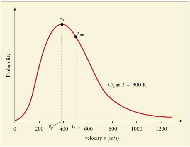
The Maxwell-Boltzmann Distribution:
The Kinetic theory of gases applies to a large number of particles.
Some molecules will be moving faster than average and some much slower.
A graph of the distribution of speeds
The Laws of Thermodynamics:
Zeroth Law of Thermodynamics: If objects 1 and 2 are in thermal equilibrium with Object 3, then Objects 1 and 2 are in thermal equilibrium with each other.
First Law of Thermodynamics:
It is a special case of the law of conservation of energy that describes processes in which only internal energy changes and the only energy transfers are by heat and work.
Δ𝑈=𝑄+𝑊ΔU=Q+W
It can be used to calculate the work done.
(𝑊=−𝑃Δ𝑉)(W=−PΔV)
Thermodynamic Processes:
Isothermal: Temperature remains constant.
Adiabatic: No transfer of heat.
Isobaric: Pressure remains constant.
Isochoric: Volume remains constant.
Second Law of Thermodynamics:
It describes how systems evolve over time.
Entropy describes it all.
It is associated with a state of randomness, disorder, or uncertainty.
The total entropy of the system and its surroundings increased.
Heat always flows from an object at higher temperature to an object at lower temperature, never the other way around.
Example: What’s the value of 𝑊W for the process ab following path 1 and for the same process following path 2 (from a to d to b), shown in the 𝑃–𝑉P–V diagram below?

Solution.
Path 1. Since, in path 1, 𝑃P remains constant, the work done is just −𝑃Δ𝑉−PΔV:
𝑊=−𝑃Δ𝑉=−(1.5×10⁵ Pa)[(30×10−3 m3)−(10×10−3m3)]=−3,000 JW=−PΔV=−(1.5×10⁵ Pa)[(30×10−3 m3)−(10×10−3m3)]=−3,000 J
Path 2. If the gas is brought from state 𝑎a to state 𝑏b, along path 2, then work is done only along the part from 𝑎a to 𝑑d. From 𝑑d to 𝑏b, the volume of the gas does not change, so no work can be performed. The area under the graph from 𝑎a to 𝑑d is
𝑊=−12ℎ(𝑏1+𝑏2)𝑎𝑚𝑝;=−12(Δ𝑉)(𝑃𝑎+𝑃𝑑)𝑎𝑚𝑝;=−12(20×10−3 m3)[(1.5×10⁵ Pa)+(0.7×10⁵ Pa)]𝑎𝑚𝑝;=−2,200 JW=−21h(b1+b2)amp;=−21(ΔV)(Pa+Pd)amp;=−21(20×10−3 m3)[(1.5×10⁵ Pa)+(0.7×10⁵ Pa)]amp;=−2,200 J
Heat Engines:
It is a device which uses heat to produce useful work.
For any cyclic heat engine, some exhaust heat is always produced. It’s impossible to completely convert heat into useful work.
Working: Energy in form of heat comes into the engine from a high temp source, some of this energy is converted in to useful work, the remains are ejected as exhaust heat. Then, the cycle returns to original state and the cycle resumes again.
Example: A heat engine draws 800 J of heat from its high-temperature source and discards 450 J of exhaust heat into its cold-temperature reservoir during each cycle. How much work does this engine perform per cycle?
Solution. The absolute value of the work output per cycle is equal to the difference between the heat energy drawn in and the heat energy discarded:
∣𝑊∣=𝑄H−∣𝑄C∣=800 J−450 J=350 J∣W∣=QH−∣QC∣=800 J−450 J=350 J
Heat Transfer:
There are three ways in which the heat is transferred:
Conduction
Convection
Radiation
Conduction:
Radiation Heat conducts from one point to another only if there is a temperature difference between the two objects.
The rate at which heat is transferred is given by:
𝑄Δ𝑡=𝑘𝐴Δ𝑇𝐿ΔtQ=LkAΔT
Convection: The movement caused within a fluid by the tendency of hotter and therefore less dense material to rise, and colder, denser material to sink under the influence of gravity, which consequently results in transfer of heat.
Radiation:
Emission or transmission of energy in the form of waves or particles through space or through a material medium.
Unit 3: Electric Force, Field, and Potential
Electric Charge:
In an isolated system, charge is always conserved.
Protons and electrons have a quality called electric charge.
Charge is invariant in nature (value of charge doesn’t depend on frame of reference).
Charge is quantised (it means any charge on the body is an integral multiple of the fundamental amount of electric charge).
Q = n e
e = 1.6 * 10^-19 C
Coulomb’s Law:
The electric force between two charged particles obeys a law that is very similar to the gravitational force between two masses. So, called inverse square laws.
Electric force between two particles with charges q1 and q2, separated by distance r, has a magnitude by the equation:
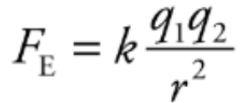
The value of the proportionality constant k, depends on the material between the charged particles. Generally, called a Coulomb’s constant.
k0 = 9 * 10^9 N. m^2/C^2 written as,
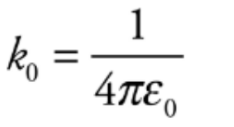
e0 is known as the permittivity of free space.
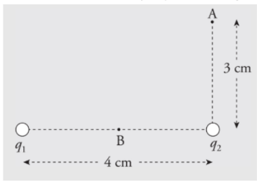
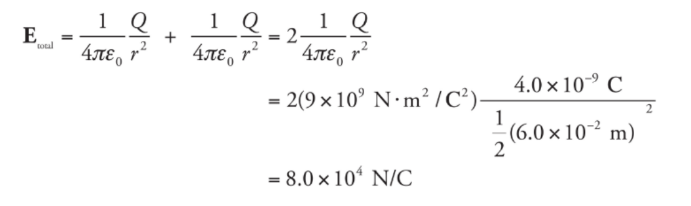
Example: A dipole is formed by two point charges, each of magnitude 4.0 nC, separated by a distance of 6.0 cm. What is the strength of the electric field at the point midway between them?
Solution. Let the two source charges be denoted +Q and -Q. At Point P, the electric field vector due to +Q would point directly away from +Q, and the electric field vector due to -Q would point directly towards -Q. Therefore, these two vectors point in the same direction (from +Q to -Q), so their magnitudes would add.

Using the equation for the electric field strength due to a single point charge, we find that
Example: Consider the proton and electron in hydrogen. The proton has a mass of 1.6 × 10⁻²⁷ kg and a charge of +e. The electron has a mass of 9.1 ×10⁻³¹ kg and a charge of −e. In hydrogen, they are separated by a Bohr radius, about 0.5 × 10⁻¹⁰ m. What is the electric force between the proton and electron in hydrogen? What about the gravitational force between the proton and electron?
Solution. The electric force between the proton and the electron is given by Coulomb’s Law:
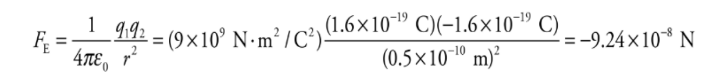
The fact that FE is negative means that the force is one of attraction, which we naturally expect, since one charge is positive and the other is negative. The force between the proton and electron is along the line that joins the charges, as we’ve illustrated below. The two forces shown form an action/reaction pair.
 Now, the gravitational force between the two charges is given by Newton’s Law of Gravitation:
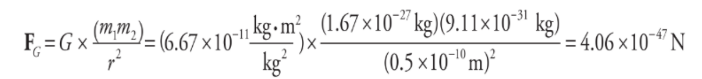
Now, compare the orders of magnitude of the electric force to the gravitational force. The electric force has an order of magnitude of 10^-8 N, but the gravitational force has an order of magnitude of 10^-47 N! This means that the electric force is something like 10³9 times larger! This is the reason that in problems where we calculate electrostatic forces, we often neglect gravitational forces.
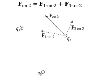
Addition of forces:
Consider three point charges: q1, q2, and q3. The total electric force acting on, say, is simply the sum of F1-on-2, the electric force on q2 due to q1, and F3-on-2, the electric force on q2 due to q3:
Example: Consider four equal, positive point charges that are situated at the vertices of a square. Find the net electric force on a negative point charge placed at the square’s center.
Solution: Refer to the diagram below. The attractive forces due to the two charges on each diagonal cancel out: F1 + F3 = 0, and F2 + F4 = 0, because the distances between the negative charge and the positive charges are all the same and the positive charges are all equivalent. Therefore, by symmetry, the net force on the center charge is zero.

Electric Field:
The space is surrounded by a charge in which another charged particle experiences the force.
The electric field vector E:

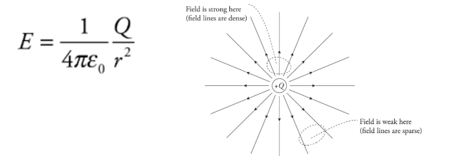
The strength of the electric field created by a point-charge source of magnitude Q. This is the electric field surrounding a point charge.
Example: A charge q = +3.0 nC is placed at a location at which the electric field strength is 400 N/C. Find the force felt by the charge q.
Solution. From the definition of the electric field, we have the following equation:
 Therefore, in this case, F on q = qE = ( 3× 10^-9 C)(400 N/C) = 1.2 × 10^-6 N.
There are three types of electric fields:
Radial field: this occurs from a point charge/ charged sphere.
These fields are inversely proportional to the square of the distance from the point charge.
The second type of field is generated by a collection of point charges with specified locations and charges:
Here, the results in an electric field are determined by superposition.
The third type of field is an infinite sheet of charge:
It is constant in both magnitude and direction.
The electric fields follow same properties as the electric force.
The electric field lines never cross.
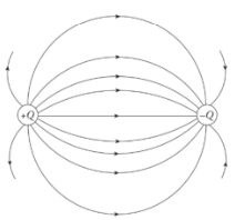
Electric field lines always point away from positive source charges and toward negative ones. The pair is called an electric dipole.
Electric field is always perpendicular to the surface, no matter what shape the surface may be.
The Uniform Electric Field:
A lot of problems deal with uniform electric fields.
The field may be taken as uniform at least in the middle.
Uniform field just signifies the constant force.
Example: Positive charge is distributed uniformly over a large, horizontal plate, which then acts as the source of a vertical electric field. An object of mass 5 g is placed at a distance of 2 cm above the plate. If the strength of the electric field at this location is 106 N/C, how much charge would the object need to have in order for the electrical repulsion to balance the gravitational pull?
Solution. Clearly, since the plate is positively charged, the object would also have to carry a positive charge so that the electric force would be repulsive.
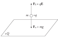 Let q be the charge on the object. Then, in order for Fe to balance mg, we must have

Conductors and Insulators:
Conductors: Materials that generally allow the flow of excess charge without resisting it.
Metals, aqueous solutions, etc.
Insulators: Materials which resist the flow of electrons.
Glass, rubber, wood, and plastic.
Methods of Charging:
Through charging by friction:
It involves rubbing the insulator against another material, thereby stripping electrons from one to another material.
Through conduction:
When we connect two conductors charge flows from one to another until the potential of both the conductors becomes the same.

Through induction: The process of charging by induction may be used to redistribute charges among a pair of neutrally charged spheres.
In the end, both spheres are charged.
Let’s imagine two neutrally charged spheres that are set on an insulating stand. They are in contact with each other.
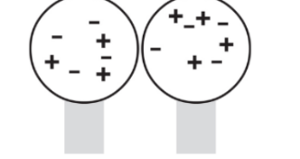
When a charge is brought near one of the spheres then, excess negative charges are located on the right sphere and positive excess charges are at the left sphere.
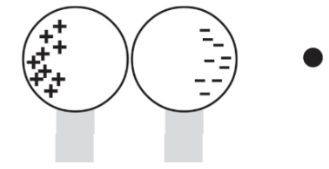
When the external charge is still nearby, the two conducting spheres are separated. Because the conductors are no longer in contact, the negative charge has been trapped on the right sphere and the positive charge has been trapped on the left sphere.
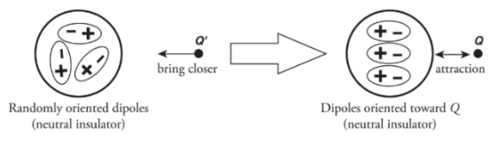
Note: the net charge is unchanged but, the distribution of charges is changed.If the sphere was made up of glass (an insulator):
There aren’t any free electrons.
The atoms that make up the sphere will become polarised.
Electrical Potential Energy:
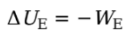
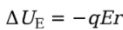
WE is the work done by the electric force, then the change in the charge’s electrical potential energy is defined by:
Example: A positive charge +q moves from position A to position B in a uniform electric field E: What is its change in electrical potential energy?
Solution. Since the field is uniform, the electric force that the charge feels, FE = qE, is constant. Since q is positive, FE points in the same direction as E, and, as the figure shows, they point in the same direction as the displacement, r. This makes the work done by the electric field equal to We = FEr = qEr, so the change in the electrical potential energy is
Note that the change in potential energy is negative, which means that potential energy has decreased; this always happens when the field does positive work. It’s just like dropping a rock to the ground: Gravity does positive work, and the rock loses gravitational potential energy.
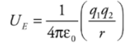
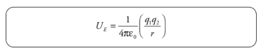
Electrical Potential Energy from a Point Charge:
Electrical potential energy required to move along the field lines surrounding a point charge is given by:
Example: A positive charge q1= +2 × 10⁻⁶ C is held stationary, while a negative charge, q2 = −1 × 10⁻⁸ C, is released from rest at a distance of 10cm from q1. Find the kinetic energy of charge q2 when it’s 1 cm from q1.
Solution. The gain in kinetic energy is equal to the loss in potential energy; you know this from the Conservation of Energy. Previously, we looked at constant electric fields and were able to use the equation for work from a constant force. However, when the field (and therefore the force) changes, we need another equation. Electrical potential energy required to move along the field lines surrounding a point charge is given by:
 Therefore, if q1 is fixed and q2 moves from rA to rB, the change in potential energy is
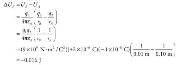 Since q2 lost 0.016 J of potential energy, the gain in kinetic energy is 0.016 J. Since q2 started from rest (with no kinetic energy), this is the kinetic energy of q2 when it’s 1cm from q1.
Electric Potential:
It is a scalar property of every point in the region of the electric field. At a point in the electric field potential is defined as the interaction of a unit positive charge. If at a point in the electric field, a charge q has potential energy U, then the electric potential at that point can be given as

Electric potential is electrical potential energy per unit charge, and the units of electric potential are joules per coulomb.
Electrical Potential Energy from a Point Charge:
Consider the electric field created by a point source charge Q. If a charge q moves from a distance rA to a distance rB from Q, then the change in the potential energy is:

The difference in the electric field between positions A and B in the field created by Q is:

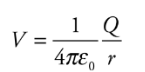
If Va tends to zero and ra tends to infinity, then for a point charge Q, the electric potential at a distance r from Q is:
 Note: Electric Potential and Electric Potential Energy, although very closely related and have similar names, are not the same thing. Even the units are measured differently—the electric potential is measured in joules per coulomb and the electric potential energy is in joules.
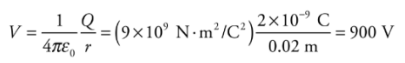
Example: Let Q = 2 × 10⁻⁹ C. What is the potential at a Point P that is 2 cm from Q?
Solution. Relative to V = 0 at infinity, we have
Equipotential surfaces:
They are the surfaces of constant potential.
The equipotentials are always perpendicular to the electric field lines.
Addition of Electric Potential:
The formula V = kQ/r helps us to find the potential due to a single point source charge, Q.
Potential is scalar.
So, when adding up the potential it is simply adding numbers and nothing complicated like adding up the vectors.
When calculating the change in potential energy, the change in positions should be kept in mind.
Example: How much work would it take to move a charge q = +1 × 10⁻² C from Point A to Point B (the point midway between q1 and q2)?
Solution.
ΔUΕ = qΔV, so if we calculate the potential difference between Points A and Band multiply by q, we will have found the change in the electrical potential energy. Then, since the work by the electric field is −ΔU, the work required by an external agent is ΔU. First, we need the potential at point A, VA. Since there are two charges q1 and q2 contributing to the potential at point A, we calculate the contribution of each using and sum the results. Remember that the potential is a scalar quantity and so no vector addition is required here. It is very important to keep track of the positive and negative signs, however.
 A similar calculation can be carried out for point B, although the distance from the charges will be different for point B than they were for point A.

Δ VA → B = VB - VA = (-900 V) - (-1080 V) = +180 V. This means that the change in electrical potential as q moves from A to B is
 This is the work required by an external agent to move q from A to B.
Equipotential Curves and Equipotential Maps:
Equipotential Curve: Equipotential curves are curves of constant elevation. If you walk along any of the contour lines and you neither ascend or descend, then the curve is known as the equipotential curve.
Equipotential Map: A drawing of several equipotential curves at various values of the potential for a charge distribution is called an equipotential map.

Both equipotential maps are made of concentric circles.
Everywhere, the equipotential curves meet the field lines, and the two curves meet at a right angle.
The equipotential map for an isolated positive charge is exactly the same as that for an isolated negative charge.
 The equipotential map and some electric field lines for an electric dipole
The electric field is strong where the field lines which are solid here are densely packed and weak where they are spread out.
The equipotential map shows lines at a constant voltage difference ΔV, so the field strength, is strong when the distance, r, between the lines is small.

The Electric Potential of a uniform field:
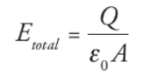
Example: Consider a very large, flat plate that contains a uniform surface charge density σ. At points that are not too far from the plate, the electric field is uniform and given by the equation:
 What is the potential at a point which is a distance d from the sheet (close to the plates), relative to the potential of the sheet itself?
Solution. Let A be a point on the plate and let B be a point a distance d from the sheet. Then
 Since the field is constant, the force that a charge q would feel is also constant, and is equal to
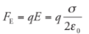 Therefore,
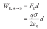
so applying the definition gives us
 This says that the potential decreases linearly as we move away from the plate.
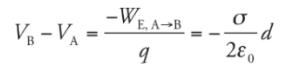
Example: Two large flat plates—one carrying a charge of + Q, the other −Q—are separated by a distance d. The electric field between the plates, E, is uniform. Determine the potential difference between the plates.
Solution. Imagine a positive charge q moving from the positive plate to the negative plate:

Since the work done by the electric field is
 the potential difference between the plates is
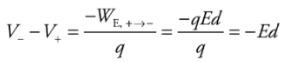 This tells us that the potential of the positive plate is greater than the potential of the negative plate, by the amount Ed. This equation can also be written as
 Therefore, if the potential difference and the distance between the plates are known, then the magnitude of the electric field can be determined quickly. The magnitude is simply
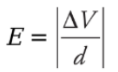
Capacitors and Capacitance:
Capacitor: Two conductors, separated by some distance that carry equal but opposite charges +Q and -Q. The pair comprises a system called a capacitor.
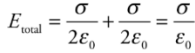
Parallel-Plate capacitor: The capacitor is in the form of parallel metal plates or sheets.

Therefore, with two plates, one with surface charge density +σ, and the other−σ, the electric combines to give a field that’s zero outside the plates and that has magnitude
Capacitance: Q is the total charge stored on either plate of a capacitor, and ΔV is the potential difference between the plates. The ratio of Q to ΔV, for any capacitance, is defined as its capacitance.
C = Q/ΔV
The capacitance measures the capacity for holding charge.
For a parallel-plate capacitor we get:
Electric Field and Capacitors:
The electric field E always points from the positive plate towards the negative plate, and the magnitude remains the same at every point between the plates.
Uniform electric is approximately true because the electric field is constant everywhere only in an infinitely large sheet of charge which is quite impossible to construct.
ΔV = Ed
Fringing Fields:
The plates of the capacitor are infinitely large.
Analysis is good near the center of the plates than the edges.
For areas beyond the edges, we approximate the field as the sum of the capacitor field and a dipole formed by the charges at the edges of the p
Energy stored in Capacitor:

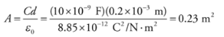
Example: A 10-nanofarad parallel-plate capacitor holds a charge of magnitude 50 μC on each plate. (a) What is the potential difference between the plates? (b) If the plates are separated by a distance of 0.2 mm, what is the area of each plate?
Solution
a) From the definition, C = Q/ΔV, we find that

b) Because K = 1, we have the equation C = ε0A/d, and can calculate the area, A, of each plate:
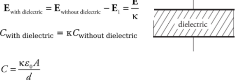
Capacitors and dielectric:
To keep the plates of the capacitor apart they are filled with dielectric which increases the capacitance of the capacitor.
Note: Why can’t we use a conductor?
If a conductor is placed between the plates, the charges are no longer separated and the device is no longer a capacitor.
Unit 4: Electric Circuits
Electric Current:
It comprises an energy source typically a battery, one or more conducting materials, and circuit components such as resistors and capacitors.
Current;
Continous flow of charge
Current is the charge per unit of time expresssed in coulumb per second (ampere)
Average Current:
Battery and Voltage:
A battery is a device that maintains an electric potential difference between the two terminals.
The battery could consist of a single cell or multiple cells.
A voltage difference between two points in a conducting material causes a charge to flow.
The voltage is measured in volts.
As long as the potential difference is maintained, the flow of charge will continue.
The flow is from higher potential to lower potential. The electricity also flows in that direction called direct current.
Resistors and Resistance:
Resistance: It is the impedance to the flow of electricity through a material. As a charge moves through a material, it eventually hits a non-moving nucleus in the material.
Resistivity: It can be thought of as the density of nuclei the electrons may strike.
R = ρ l / A
This equation is applied to shapes with uniform cross-sectional areas and cannot be applied to those with varying cross-sectional areas.
Example: A wire of radius 1 mm and length 2m is made of platinum(resistivity = 1 × 10⁻⁷Ω·m).
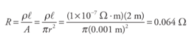
Resistance is measured in ohms (Ω)
Resistivity is measured in ohm-meters (Ωm)
Materials with:
Low resistivity: conductors
High resistivity: insulators
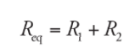
Combining Resistors and Equivalent Resistance:
Equivalent resistance: When two or more resistors are combined mathematically, the resulting resistance is called equivalent resistance.
In arrangements of three or more resistors, it is possible for the arrangement to be a mixture of series and parallel. It can be solved accordingly to find the equivalent resistance.
Resistors in Series:
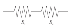
It can be thought of as a single wire of a greater length.
Resistors arranged in series result in an overall resistance that is greater than the resistance of any individual resistors in the arrangement.
Example: A resistor having an electrical resistance value of 100 ohms, is connected to another resistor with a resistance value of 200 ohms. The two resistances are connected in series. What is the total resistance across the system?
Solution:
R1 = 100 ohm
R2 = 200 ohm
Req = R1 + R2 = 300 ohm
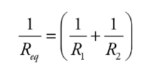
Resistors in parallel:
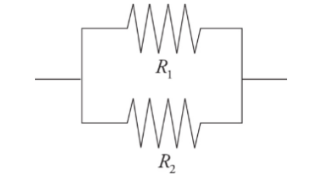
They behave like a wire with a greater cross-sectional area.
Resistors arranged in parallel result in an overall resistance that is less than any of the resistors.
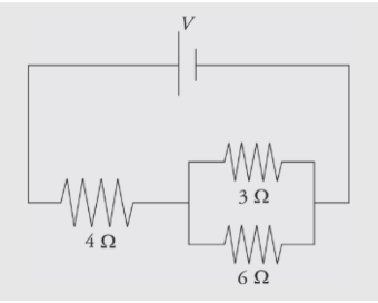
Example: Calculate the equivalent resistance for the following circuit:
 Solution:
First, you see that the three resistors are not purely in parallel or purely in series. There must be a pair which is purely in parallel or series. The current that flows through the 4 Ω could flow through the 3 Ω or 6 Ω resistor, so none of the resistors are purely parallel. However, the no current that flows through the 3 Ω can flow through the 6 Ω because of the junction before that combination, so those two resistors are purely parallel. You find the equivalent resistance of the two parallel resistors:
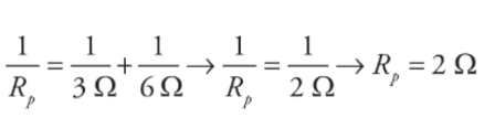
The current that flows into the 4 Ω must flow into this equivalent resistor, so this resistance is in series with the 4Ω resistor. The total equivalent resistance in the circuit is R= 4 Ω + 2 Ω =6 Ω. The reason for considering these equivalent resistances is because the easiest problem to solve is the simple, one-resistor problem presented originally. You can represent many combinations of resistors in series or parallel as a single equivalent resistor, and then use Ohm’s Law to solve for the current that flows out of the battery into the circuit.
Measuring Current and Voltage in a circuit:
Ammeter: It is a device with a very low resistance that measures the current.
Voltmeter: It measures the electric potential difference called the potential drop.
Ohm’s Law:
It shows the relationship between potential differences and current.
V = IR
R is the resistance in the circuit.
V is the potential difference in the circuit
I is the electric current
Example: If a voltage of 9 V is applied between the ends of the wire from example 1, and the wire is Ohmic, what will be the resulting current?
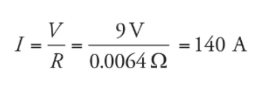
Power Dissipation:
The power dissipated by a circuit component is given by the product of the current through the component and the voltage drop across it.
P = VI
P = I2R
P = V2IR
P is the power
V is the potential difference in the circuit.
I is the electric current.
Example: A 9V battery is connected to a resistor having a resistance of 10 Ω.What is the current and power across the resistor?
Solution:
I = V/R = 9/10 = 0.9 A
P = VI = 9 × 0.9 = 8.1 J/s or 8.1 W
Kirchhoff’s Law:
It is used when analysing the circuits.
The loop rule states that the voltage drop across any complete loop in a circuit is 0V.
This statement follows from the conservation of energy when applied to circuits.
The junction rule states that the sum of all current flowing into any junction is equal to the current flowing out of the junction.
This statement follows from the conservation of charge.
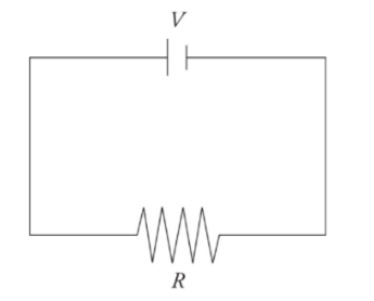
A very simple circuit:
simple circuit consists of one battery with voltage V and one resistor of resistance R connected by wires.
EMF and Internal Resistance:
The voltage supplied by an ideal battery is referred to as EMF (electromotive force).
A battery in a circuit can be modelled as an ideal EMF in series with a resistor. In this model, r is called the internal resistance of the battery.
The voltage measured across the EMF source is called the terminal voltage.
Capacitors in the circuit:
A capacitor stores energy in an electric field.
A parallel-plate capacitor consists of two plates of area A and separation d.
Capacitance determines the amount of charge that can be stored on the plates for a given voltage
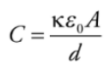
C = k ε0 A/d
Capacitance is measured in a unit called farad.
The ratio of the charge on either plate to the voltage across the plates is capacitance.
Δ V = Q/C
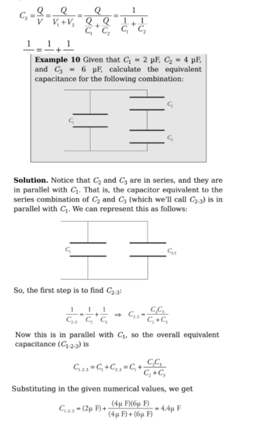
Combination of Capacitors and Equivalent Capacitance:
Capacitors in parallel:
 Capacitors in series:
Charging and Discharging:
An uncharged capacitor may be charged by connecting it to a battery. After the connection is made, the uncharged capacitor has a potential difference of 0 V.
A charged capacitor may be discharged by connecting the two plates to a resistor.
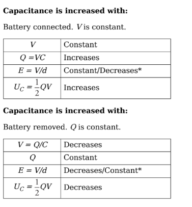
Altering the capacitance of a capacitor:
The capacitance is given by:
C = k ε0 A/d
There are two scenarios for making these changes to a charged capacitor in a circuit:
The battery may remain connected, causing the potential difference to remain constant.
The battery may be disconnected, causing the charge on each plate to remain constant
RC Circuits with Capacitors in Steady State:
When a capacitor is discharged, the voltage between the plates is 0V. As a result, it acts like a wire.
The discharged capacitor short circuits any resistors arranged in parallel with the capacitor.
The situation is reversed when the capacitor is fully charged. It acts like a broken wire.
The fully charged capacitor short circuits and resistors arranged in series with the capacitor.
Example: Determine the current through and the voltage across each electrical device in the following circuit when
a) the switch has just been closed
b) the switch has been thrown for a long period of time
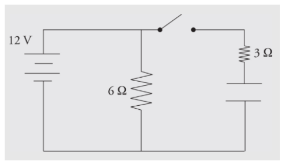
a) When the switch has just been closed, the capacitor is treated like a wire with no resistance. The circuit behaves like a simple parallel circuit. There are 12 V across the 6 Ω resistor, so 2 amps of current flow through it. There are 12 V across the 3 Ω resistor, so 4 amps flow through it. By Kirchhoff’s Law, the currents add 6 amps through the battery, and the equivalent resistance of the circuit is 2 Ω.b) After the switch has been closed for a long period of time, the capacitor behaves like an infinite resistor. There are still 12 V across the 6 Ω resistor, so 2 amps of current will still flow through it. If the capacitor behaves like an infinite resistor, no current can flow through that branch. There will be no current through the 3 Ω resistor. The capacitor will have 12 V across it, and there will be no voltage across the 3 Ω resistor (otherwise current would be flowing through it). The current will be 2 amps through the battery, and the equivalent resistance of the circuit is 6 Ω.
Unit 5: Magnetism and Electromagnetic Induction
Magnetic Field:
The space surrounding a magnet is called magnetic field.
The direction is defined as pointing out of the north end of a magnet and into the south end of a magnet.

To visualise the magnetic field we use magnetic field lines.
Magnetic field lines emanate from or enters in the surface of a magnetic material at any angle.
Magnetic field lines exist inside every magnetised material.
Magnetic field lines can be mapped by using iron dust or using compass needle.
We use (x) when the magnetic field goes into the plane.
We use (.) when the magnetic field goes out of the plane.
There are no monopoles as they always exist in pairs.
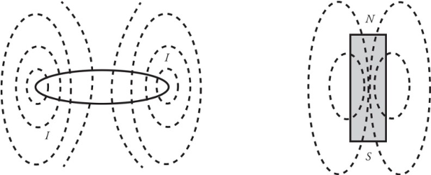
Bar Magnets:
A permanent bar magnet creates a magnetic field that closely resembles the magnetic field produced by a circular loop of current-carrying wire.
The magnetic field created by a permanent bar magnet is due to the electrons.
All materials have some magnetic permeability which determines how great a magnetic field an object will develop.
Magnetic poles repel each other when they are the same and opposite poles attract each other.

The magnetic force on a moving charge:
If a particle with charge q moves with velocity v through a magnetic field B, it will experience a magnetic force, Fb:
𝐹𝐵=𝑞𝑣∗𝐵FB=qv∗B
With magnitude:
𝐹𝐵=∣𝑞∣𝑣𝐵sin𝜃FB=∣q∣vBsinθ
If angle = 90 degrees, it is the max value.
0 or 180, velocity and magnetic field are parallel or antiparallel, here the magnetic force is zero.
Right-Hand Rule:
Whenever you use the right-hand rule, follow these steps:
1. Orient your hand so that your thumb points in the direction of the velocity v. If the charge is negative, turn your thumb by 180 degrees.
2. Point your fingers in the direction of B.
3. The direction of FB will then be perpendicular to your palm.

Example 1: For each of the following charged particles moving through a magnetic field, determine the direction of the force acting on the charge.

Solution:
If you point your fingers to the top of the page and thumb to the right of the page, your palm should point out of the page. The force is out of the page.
If you point your fingers into the page and thumb to the top of the page, your palm should point to the left of the page. The force is to the left of the page.
If you point your fingers into the page and thumb to the right of the page (remember, when the charge is negative, your thumb points in the opposite direction from the velocity), your palm should point to the bottom of the page. The force of a positive charge would be toward the bottom of the page, but because this is a negative charge, the force points up.
Example 2: A charge +q = +6 × 10⁻⁶ C moves with speed v = 4 × 10⁵ m/s through a magnetic field of strength B = 0.4 T, as shown in the figure below. What is the magnetic force experienced by q?

Solution: the magnitude of 𝐹𝐵FB is 𝐹𝐵=𝑞𝑣𝐵sin𝜃=(6×10⁻⁶𝐶)(4×10⁵𝑚/𝑠)(0.4𝑇)sin30=0.48𝑁FB=qvBsinθ=(6×10−6C)(4×105m/s)(0.4T)sin30=0.48N. By the right hand rule, the direction is into the plane of the page, which is symbolized by x.
The magnetic force on a current-carrying wire:
Let a wire of length l be immersed in magnetic field B. I the wire carries current I, then the force on the wire is,
𝐹𝐵=𝐼𝑙×𝐵FB=Il×B
With magnitude:
𝐹𝐵=𝐵𝐼𝑙sin𝜃FB=BIlsinθ
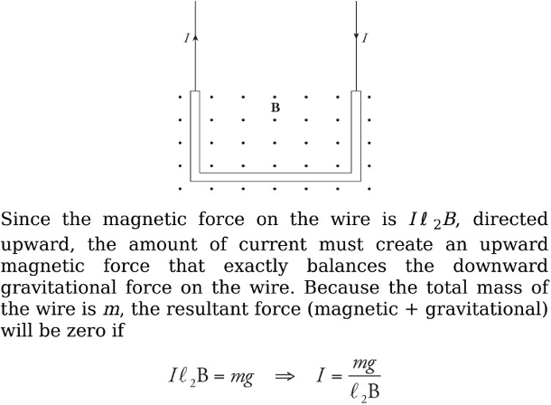
Example: A U-shaped wire of mass m is lowered into a magnetic field B that points out of the plane of the page. How much current I must pass through the wire in order to cause the net force on the wire to be zero?
Solution. The total magnetic force on the wire is equal to the sum of the magnetic forces on each of the three sections of wire. The force on the first section (the right, vertical one), FB1, is directed to the left (applying the righthand rule, and the force on the third piece (the left, vertical one), FB3, is directed to the right. Since these pieces are the same length, these two oppositely directed forces have the same magnitude, Il 1B = Il 3B, and they cancel. So the net magnetic force on the wire is the magnetic force on the middle piece. Since I points to the left and B is out of the page, the right-hand rule tells us the force is upward.
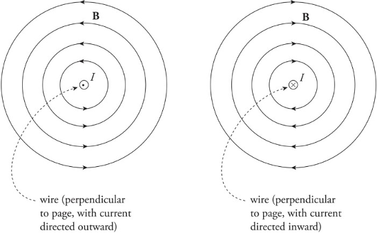
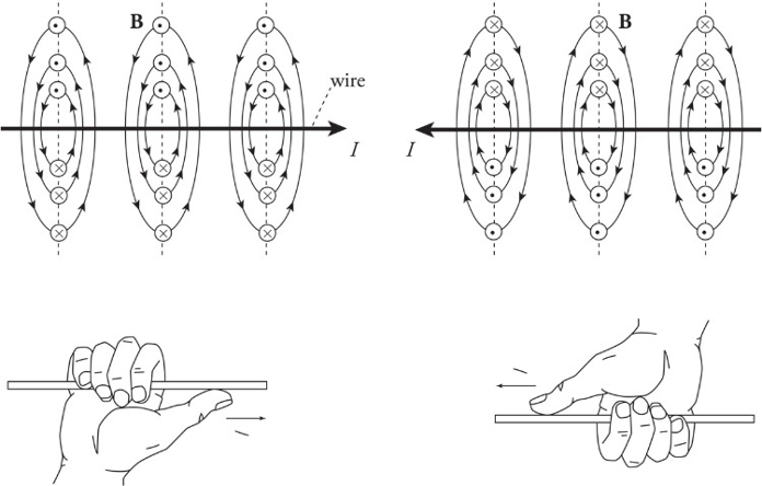
Magnetic fields created by current-carrying wire:
Magnetic fields are unending loops.
The direction of the circles is determined by the right-hand rule.
𝐵=𝜇02𝜋𝐼𝑟B=2πμ0rI
𝜇0μ0 is the permeability of free space.
𝜇0=4𝜋×10−7=𝑁/𝐴2=4𝜋×10−7𝑇∗𝑚/𝐴μ0=4π×10−7=N/A2=4π×10−7T∗m/A
Right-hand rule for the magnetic field created by a current-carrying wire:
1. Put your thumb in direction of current or in direction of a positive traveling charge.
2. Grab the wire/path.
3. As the fingers curl around your thumb, it represents the magnetic field going around the wire/path.
Example: The diagram below shows a proton moving with a speed of 2×10⁵𝑚/𝑠2×105m/s, initially parallel to, and 4 cm from, a long, straight wire. If the current in the wire is 20 A, what’s the magnetic force on the proton?
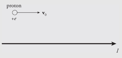
Solution. Above the wire (where the proton is), the magnetic field lines generated by the current-carrying wire point out of the plane of the page, so 𝑣0×𝐵v0×B points downward. Since the proton’s charge is positive, the magnetic force 𝐹𝐵=𝑞(𝑣0×𝐵)FB=q(v0×B) is also directed down, toward the wire.

Solenoids create uniform fields:
Magnetic fields are unending loops.
Solenoid is a device that is constructed by a series of coaxial wires through which a continuous current flows.
Solenoid is an electromagnet.
The field inside a solenoid inside a laboratory is very uniform in both direction and strength.
When there is no current, there is no magnetic field.
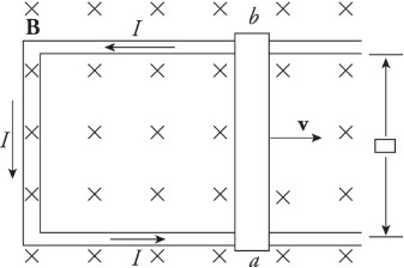
Motional EMF:
The simple act of moving a conducting rod in the presence of an external magnetic field that creates an electric field within the rod.
The presence of a moving conductor inside the magnetic field results in the creation of an electric field that points in the same direction as the magnetic force on the electrons.
The figure shows a conducting wire of length l moving with constant velocity v in the plane through a uniform magnetic field perpendicular to the page. This induced electric field points downward.
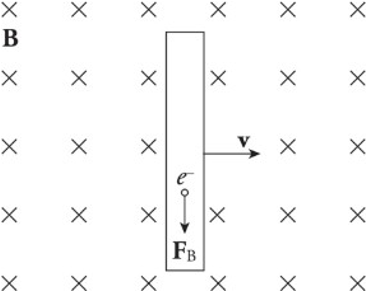
As long as the rod continues to move at velocity v, the electric field will be maintained within the rod.
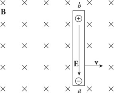
A charge q in the wire feels two forces:
Electric force: 𝐹𝑒=𝑞𝐸Fe=qE
Magnetic force: 𝐹𝑏=𝑞𝑣𝐵Fb=qvB (sin 90 degrees = 1)
If q is negative, Fe is upward and Fb is downward.
If q is positive, Fe is downward and Fb is upward.
Once the magnitude of Fe equals the magnitude of Fb, the charges in the wire are in electromagnetic equilibrium.
𝑞𝐸=𝑞𝑣𝐵qE=qvB
𝐸=𝑣𝐵E=vB
The presence of the electric field requires a potential difference between the ends of the rod. The potential difference Vba is equal to Eℓ and, since E = vB, the potential difference can be written as vBℓ.
Induced Current:
An induced current is created in three ways:
Changing the area of the loop of wire in a stationary magnetic field.
Changing the magnetic field strength through a stationary circuit.
Changing the angle between the magnetic field and the wire loop.
Each of these changes causes a change in flux. The motion of a sliding rod through the magnetic field creates an electromotive force, called motional emf.
𝜀=𝐵𝑙𝑣ε=Blv
An external agent must provide this same amount of force to the right to maintain the rod’s constant velocity.
The power that the external agent must supply is 𝑃=𝐹𝑣=𝐼ℓ𝐵𝑣P=Fv=IℓBv, and the electrical power delivered to the circuit is 𝑃=𝐼𝑉𝑏𝑎=𝐼𝜀=𝐼𝑣𝐵ℓP=IVba=Iε=IvBℓ.
The two expressions are identical as the energy provided by the external agent is transformed first into electrical energy and then thermal energy as the conductors making up the circuit dissipates heat.
The relationship between current in a coil of wire and magnetic fields sets the basis for Faraday’s Law.
Faraday’s Law of Electromagnetic Induction:
Electromotive force can be created by the motion of a conducting wire through a magnetic field.
A current is induced when the magnetic flux passing through the coil or loop of wire changes.
Magnetic flux helps us define what the amount of field passing into the loop means.
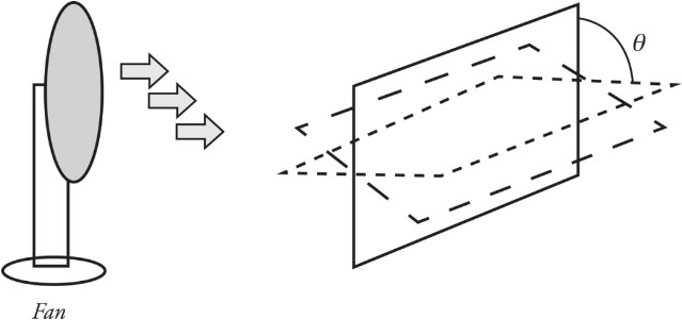
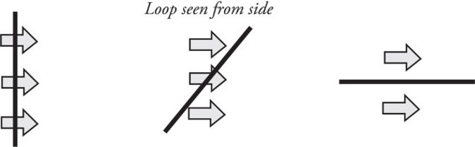
Imagine holding a loop of wire in front of a fan as shown:
The amount of air that flows through the loop depends on the area of the loop as well as its orientation (tilt angle θ).
The most effective airflow is when the loop is completely perpendicular, as in the situation to the left. The least effective is when the airflow and loop are in the situation to the right.
Θ𝐵=𝐵∗𝐴=𝐵𝐴cos𝜃ΘB=B∗A=BAcosθ
Example 1: The figure below shows two views of a circular loop of radius 3 cm placed within a uniform magnetic field, B (magnitude 0.2 T). (a) What’s the magnetic flux through the loop? (b) What would be the magnetic flux through the loop if the loop were rotated 45°? (c) What would be the magnetic flux through the loop if the loop were rotated 90°?
Solution:

According to Faraday’s Law of electromagnetic radiation, the magnitude of the emf induced in a circuit is equal to the rate of change of the magnetic flux through the circuit. This can be written mathematically in the form
∣𝜀𝑎𝑣𝑔∣=∣ΔΘ𝐵Δ𝑡∣∣εavg∣=∣ΔtΔΘB∣
Lenz’s Law: The induced current will always flow in the direction that opposes the change in magnetic flux that produced it.
It can be included mathematically with Faraday’s law of electromagnetic radiation of a minus sign:
𝜀𝑎𝑣𝑔=−ΔΘ𝐵Δ𝑡εavg=−ΔtΔΘB
Example 2: The circular loop of Example 1 rotates at a constant angular speed through 45° in 0.5 s. (a) What’s the induced emf in the loop? (b) In which direction will current be induced to flow?

Solution: The current will flow only while the loop rotates, because emf is induced only when magnetic flux is changing. If the loop rotates 45° and then stops, the current will disappear.

Unit 6: Geometric and Physical Optics
Introduction:
Electromagnetic Waves range from radio waves to gamma rays.
EM waves can propagate through empty space.
It consists of time-varying electric and magnetic fields that oscillate perpendicular to each other and to the direction of propagation of the wave.
c = 3 x 10^8 m/s
v = f λ
An oscillating charge generates an electromagnetic wave.
EM waves are transverse waves.
The direction in which the wave’s electric field oscillates is called the direction of polarisation of the wave.
EM waves do not require a medium to propagate.
When EM waves travel through a vacuum, their speed is constant.
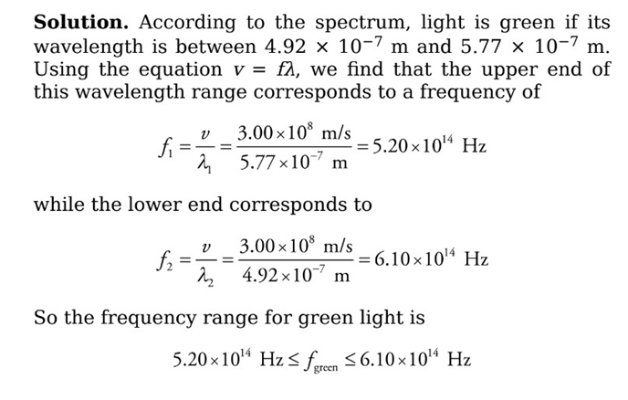
The Electromagnetic Spectrum: It can be categorized by its frequency.
The full range of waves is called the electromagnetic spectrum.

Example: What is the frequency of green light? (use v = f λ)
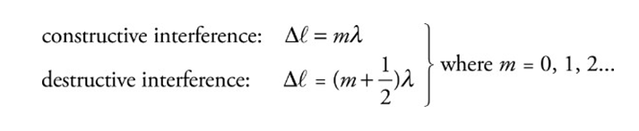
Interference and Diffraction:
The waves experience interference when they meet.
They interfere destructively or constructively depending on their relative phase.
They meet in phase (crest meets crest): combine constructively
They meet out of phase (crest meets trough): and combine destructively.
Waves are assumed to be coherent (which means their first phase difference remains constant over time and does not vary).
Young’s Double Slit Experiment:
The incident light on a barrier that contains two narrow slits, separated by distance d. On the right there is a screen whose distance from the barrier L, is much greater than d.

Diffraction: The alteration in the straight-line propagation of a wave when it encounters a barrier is called diffraction.
The waves will diffract through the slits spread out, and interfere as they travel towards the screen.
Points of interference can be seen:
Solid lines: constructive interference
Dashed lines: destructive interference


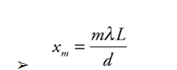
The intensity of the bright fringes decreases as m increases in magnitude.
Barriers containing thousands of tiny slits per centimeter are called diffraction gratings.
Example: For the experimental set-up we’ve been studying, assume that d = 1.5 mm, L = 6.0 m, and that the light used has a wavelength of 589 nm.
(a) How far above the center of the screen will the second brightest maximum appear?
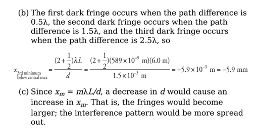
(b) How far below the center of the screen is the third dark fringe?
(c) What would happen to the interference pattern if the slits were moved closer together?

Single Slit Experiment:
A diffraction pattern will also form on the screen if the barrier contains only one slit.
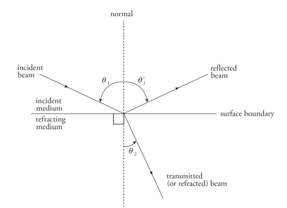
Reflection and Refraction:
The angle that the incident beam makes with the normal is called the angle of incidence.
The angle that the reflection makes with the normal is called the angle of reflection.
The angle that the transmitted beam makes with the normal is called the angle of refraction.
Laws of reflection:
The incident, reflection, and transmitted beams of light all lie in the same plane.
The relationship between incident and reflected ray:

Example: If a light ray incidents on a surface at an angle 60 degree. Then, the angle with which the reflected ray will reflect will also be 60 degree as (angle of incidence = angle of reflection).
Medium’s index of refraction:
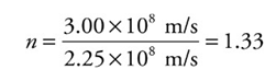
n = c/v
Example: Since the speed of light in water is v = 2.25 × 10⁸ m/s, the index of refraction of water is
 Note:
Note:
n has no units.
It is also never less than 1.
Light always travels slower in a medium than in a vacuum.
Snell’s law:
n 1 sin θ′1 = n2 sin θ′2
If n2>n1, the beam will bend/refract towards the normal.
If n2<n1, the beam will bend away from the normal.
Example: A beam of light in air is incident upon a piece of glass, striking the surface at an angle of 30°. If the index of refraction of the glass is 1.5, what are the angles of reflection and refraction?

Total Internal Reflection:
When a beam of light strikes the boundary to a medium that has a lower index of refraction, the beam bends away from the normal. As the angle of incidence increases, the angle of refraction becomes larger. At some point, when the angle of incidence reaches a critical angle, θc, the angle of refraction becomes 90°, which means the refracted beam is directed along the surface.
Total internal reflection occurs when:
n1> n2 and
θ1> θc, where θc = sin−1 (n2/n1)
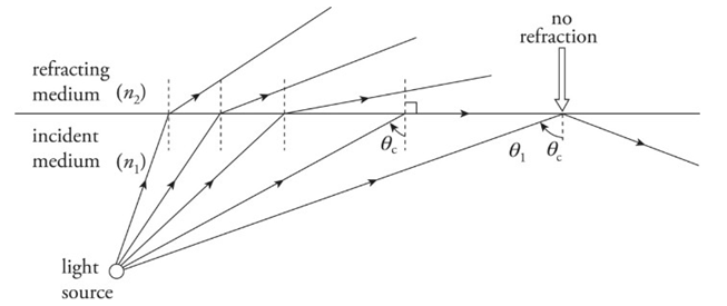
Example: What is the critical angle for total internal reflection between air and water? In which of these media must light be incident for total internal reflection to occur?

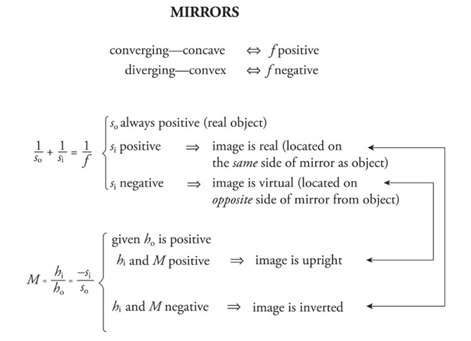
Mirrors:
A mirror is an optical device that forms an image by reflecting light.
Plane Mirror:
Light that is reflected off the mirror and is reflected back to our eyes.
The direction of the rays reflected off the mirror determines where we perceive the image to be.

Our image is behind the mirror and stands at an equal distance as we stand before the mirror.
An image is said to be real if light rays actually focus on the image. A real image can be projected onto the screen.
The images produced by the flat mirror are virtual.
In a flat mirror we see an upright image because it's virtual.
In real images the image is upside down.
The image formed by plane mirrors is neither diminished nor enlarged.
Spherical Mirrors:
A spherical mirror is a mirror that’s curved in such a way that its surface forms part of a sphere.
The center of this imaginary sphere is the mirror’s center of curvature.
The radius of the sphere is called the mirror's radius of curvature R.
Halfway between the mirror and the radius of curvature is called the focus.
The intersection of a mirror's optic axis with the mirror itself is called the vertex.
V, and the distance from V to F is called the focal length f, equal to one-half of the radius of curvature.
F = R/2
Concave mirror: A mirror whose reflective side is caved in toward the center of curvature.

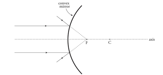
Convex mirror: A mirror whose reflective side curves away from the center of curvature.
Ray tracing for the mirrors:
Concave mirrors:
An incident ray parallel to the axis is reflected through the focus.
An incident ray that passes through the focus is reflected parallel to the axis.
An incident ray that strikes the vertex is reflected at an equal angle to the axis.
Convex mirrors:
An incident ray parallel to the axis is reflected away from the virtual focus.
An incident ray directed toward the virtual focus is reflected parallel to the axis.
An incident ray that strikes the vertex is reflected at an equal angle to the axis.
Equations:
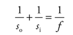
The mirror equation:
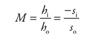
The magnification equation:
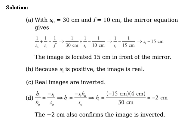
Example: An object of height 4 cm is placed 30 cm in front of a concave mirror whose focal length is 10 cm.
(a) Where’s the image?
(b) Is it real or virtual?
(c) Is it upright or inverted?
(d) What’s the height of the image?
Conclusion:
Thin Lenses:
A lens is an optical device that forms an image by refracting light.
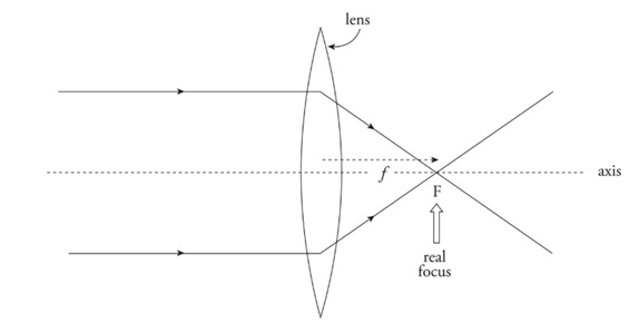
Converging lens: Bi-convex lens
Converges parallel paraxial rays of light to a focal point on the far side.
Because parallel light rays actually focus at F, this point is called a real focus. Its distance from the lens is the focal length, f.
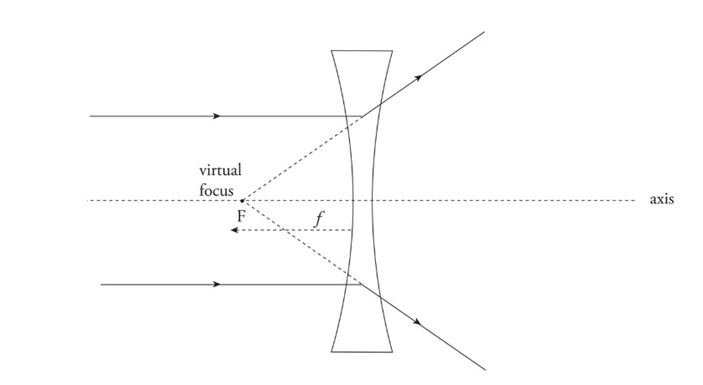
Diverging lens: Bi-concave lens
Causes parallel paraxial rays of light to diverge away from a virtual focus, F, on the same side as the incident rays.
Example: An object of height 11 cm is placed 48 cm in front of a diverging lens with a focal length of −24.5 cm.
(a) Where’s the image?
(b) Is it real or virtual?
(c) Is it upright or inverted?
(d) What’s the height of the image?
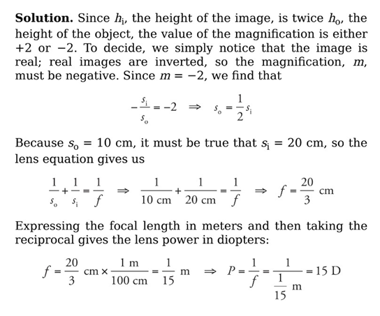
Power of Lenses:
The power of a lens, P, is defined as 1/f, where f is the lens’s focal length (in meters). Lens power is expressed in diopters (abbreviated D), where 1 D = 1 m−1.
Example: When an object is placed 10 cm from a converging lens, the real image formed is twice the height of the object. What’s the power of this lens?
Ray tracing for lenses:
Converging Lenses:
An incident ray parallel to the axis is refracted through the real focus.
Incident rays pass undeflected through the optical center, O (the central point within the lens where the axis intersects the lens).
Diverging Lenses:
An incident ray parallel to the axis is refracted away from the virtual focus.
Incident rays pass undeflected through the optical center, O.
Unit 7: Quantum, Atomic, and Nuclear Physics
Photons and the photoelectric effect
Quanta: Light being emitted as individual packets of energy called quanta.
Photon: A quantum of electromagnetic energy is known as a photon
Photoelectric effect: light behaves like a stream of photons, and this is
illustrated by the photoelectric effect
Photoelectrons: the released electrons are known as photoelectrons
Wave theory of light predicted three results:
Significant time delay between the moment of illumination and the ejection of photoelectrons.
Increasing the intensity of the light could cause the electrons to leave the metal surface with greater kinetic energy.
Photoelectrons would be emitted regardless of the frequency of the incident energy, as long as the intensity was high enough.
These predictions were not observed.
As, photoelectrons were ejected within a few billionths of a second after illumination, disproving the prediction.
Increasing the intensity of the light did not cause photoelectrons to leave the metal surface with greater kinetic energy.
For each metal there was a certain threshold frequency
E = hf
h is the Planck’s constant = 6.63 x 10^-34 J/s.
Metal’s work function is the certain amount of energy that has to be imparted to an electron on the metal surface
Kmax = hf -ϕ
fo = ϕ/ h
SI unit for energy is the joule
Example
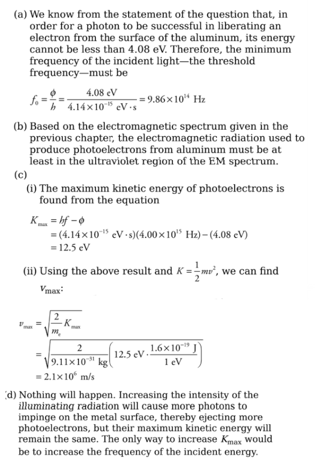
The work function, ϕ, aluminum is 4.08 eV
(a) What is the threshold frequency required to produce photoelectrons from
aluminum?
(b) Classify the electromagnetic radiation that can produce photoelectrons.
(c) If light of frequency f = 4.00 × 10¹⁵ Hz is used to illuminate a piece of
aluminum,
(i) What is Kmax, the maximum kinetic energy of ejected photoelectrons?
(ii) what’s the maximum speed of the photoelectrons? (Electron mass = 9.11×
10−31 kg.)
(d) If the light described in part (b) were increased by a factor of 2 in intensity,
what would happen to the value of Kmax?
Solution
The Bohr Model of the atom
The light from a glowing gas, passed through a prism to disperse the beam
into its component wavelengths, produces patterns of sharp lines called
atomic spectra.
R is Rydberg constant = 1.1 x 10^-7
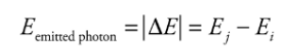
The electron absorbs a certain amount of energy, and it is excited to a higher
orbit, emitting a photon in the process.
The wavelength of the photon

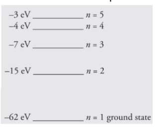
Example
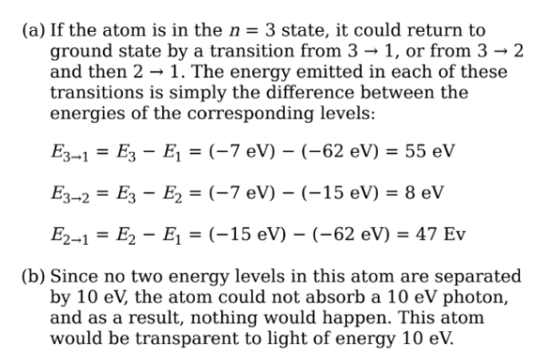
The first five energy levels of an atom are shown in the diagram
below:
(a) If the atom begins in the n = 3 level, what photon energies could be
emitted as it returns to its ground state?
(b) What could happen if this atom, while in an undetermined energy state,
were bombarded with a photon of energy 10eV?
Solution
Wave-Particle Duality
The electromagnetic radiation propagates like a wave but exchanges energy
like a particle. This is known as wave-particle duality.
De-Broglie Wavelength
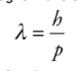
Example
Electrons in a diffraction experiment are accelerated through a
potential difference of 200 V. What is the de Broglie wavelength of these
electrons?
Solution
The Wave Function
The probability that a particle will be measured to be at a particular position
when the position is measured. That probability is related to a new physical
parameter called the wave function.
Relativity
The Theory of relativity has only two postulates:
The results of physical experiments will be the same in any
non-accelerating reference frames.
The speed of light is constant
Time dilation:
Demonstrated by synchronized atomic clocks.
E.g: When a clock placed on a fast-moving airplane is compared to a clock at rest on the ground, the clock in the airplane shows that less time has passed than the time recorded by the clock on the ground.
This is known as time dilation.
Length Contraction:
To be consistent with time dilation, there must also be disagreement
Nuclear Physics
The nucleus of an atom is composed of particles, protons, and neutrons.
Protons + Neutrons = Nucleons
The number of protons in a given nucleus is called the atom’s atomic number
denoted by Z.
The total number of nucleons (Z+N), is called the mass number, and is
denoted by A.
Isotopes: The nuclei that contain the same numbers of neutrons are called
isotopes
Notation

Example
How many protons and neutrons are contained in the nuclide?
Solution
The subscript (the atomic number, Z) gives the number of protons, which is
29. The superscript (the mass number, A) gives the total number of nucleons.
Since A = 63 = Z + N, we find that N = 63 − 29 = 34
The Nuclear Force
The strong nuclear force is a fundamental force that binds neutrons and
protons together to form nuclei.
Binding Energy
The masses of the proton and neutron:
Proton: 1.6726 x 10^-27 kg
Neutron: 1.6749 x 10^-27 kg
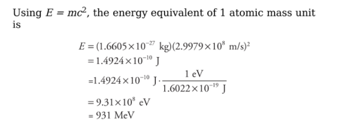
Mass defect: The difference between the mass of any bound nucleus and the
sum of the masses of its constituent nucleons is called the mass defect.
E = mc^2
Binding energy tells us how strongly the nucleus is bound
Example
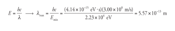
What is the maximum wavelength of EM radiation that could be used to photodisintegrate a deuteron?
Solution
The binding energy of the deuteron is 2.23 MeV,
so a photon would need to have at least this much energy
to break the deuteron into a proton and neutron. Since E =
hf and f = c/λ
Nuclear Reactions
Nuclear fusion: It is of small nuclei at extremely high temperatures.
Nuclear fission: The emission of a particle or splitting of the nucleus
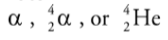
Alpha Decay
When a nucleus undergoes alpha decay, it emits an alpha particle, which
consists of two protons and two neutrons.
It is the same as the nucleus of a helium-4 atom.
An alpha particle can be represented as
Two important features of a nuclear reaction:
Mass number is conserved.
Charge is conserved.
The decaying nuclide is known as the parent.
The resulting nuclide is known as the daughter.
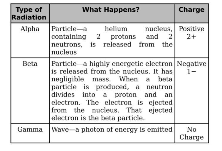
Beta Decay
There are three categories of beta decay, called β+, β−, and electron capture.
β− decay:
When the neutron-to-proton ratio is too large, the nucleus undergoes
β− decay.
It occurs when a neutron transforms into a proton and releases an
electron. The expelled electron is called a beta particle.
The transformation of a neutron into an electron and a proton, and
another particle called the electron antineutrino is caused by the
action of weak nuclear force.
β+ decay:
When the neutron-to-proton ratio is too small, the nucleus will undergo
β+ decay.
In this form of β+ decay, a proton is transformed into a neutron and a
positron, and another particle is called electron-neutrino.
Electron Capture:
In which a nucleus can increase its neutron-to-proton ratio to capture
an orbiting electron and then cause the transformation of a proton into
a neutron
Gamma Decay
In each of the decay processes defined above, the daughter was a different
element than the parent. By contrast, gamma decay does not alter the identity
of the nucleus; it just allows the nucleus to relax and shed energy.
It must emit energy in the form of a photon or a gamma ray.
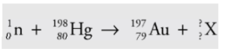
Example
A mercury-198 nucleus is bombarded by a neutron, which causes a
nuclear reaction: What’s the unknown product particle, X?
Solution
In order to balance the superscripts, we must have 1 + 198 = 197 + A, so A = 2, and the subscripts are balanced if 0 + 80 = 79 + Z, so Z = 1:

Conclusion
Disintegration Energy
Nuclear reactions must conserve total energy.
It involves the emission or absorption of energy.
A general nuclear reaction is written as:
A + B —> C + D + Q
Q is disintegration energy
If Q is positive then the reaction is exothermic.