
SCIENCE - 2nd Quarter
Ray Tracing for Spherical Mirrors
There are four special rays that are convenient to draw in locating the image formed by a spherical mirror. The intersection of any two of these rays will give us the position of the image.
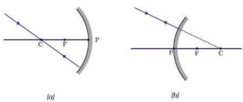
A ray passing through the center of the curvature is reflected along itself.
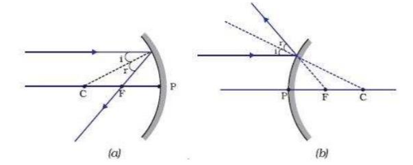
A ray parallel to the optical axis is reflected through the principal focus, as in the case of converging mirrors, or when extended, it appears to come from the principal focus, as in the case of diverging mirrors. Broken lines are used to indicate an extended ray.
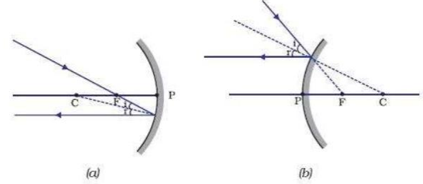
A ray passing through the focus (or which when extended passes through the focus) is reflected parallel to the optical axis.
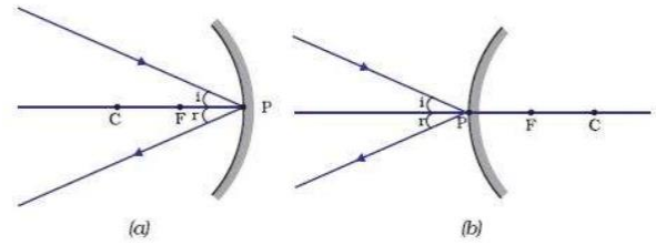
A ray striking the vertex of the mirror is reflected at an equal angle on the opposite side of the principal axis.
We can trace the image of an object formed by a spherical mirror by drawing rays emanating from one or more points of an object. Consider the tip of an object then draw incident and reflected rays. We need to draw at least two (2) of the four rays discussed. The point where the reflected rays intersect is the tip of the image. Consequently, the image of the other points of an object may be located and the image of the whole body can be traced.
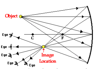
In this diagram, five incident rays are drawn along with their corresponding reflected rays. Each ray intersects at the image location and then diverges to the eye of an observer. Every observer would observe the same image location and every light ray would follow the law of reflection. Yet only two of these rays would be needed to determine the image location since it only requires two rays to find the intersection point. Of the five incident rays drawn, two of them correspond to the incident rays described by our two rules of reflection.
Summarization:
Concave mirrors are converging mirrors while convex mirrors are diverging mirrors.
There are four rays which we can draw to show the location of the image of an object reflected on spherical mirrors:
a). rays that pass through the center of the curvature
b). rays parallel to the optical axis
c). rays passing through the focus and
d). rays that strike the vertex of the mirror.
With the use of ray diagrams, we can describe the size of the image compared to the object, its location and we can also determine if the image will appear inverted or upright, real or virtual.
Reflection of Light
The history of mirrors is as old as the human race because of man’s instinct to see his image. Ancient forms of manmade mirrors came in the form of polished metals or polished stones. Ancient Greeks Egyptians and Romans had bronze or silver mirrors then crude mirrors were then introduced somewhere in 1300. Mercury was used as reflective film at first then later on it was replaced by metallic silver. But not long after aluminum was discovered to be as efficient as silver (as a reflective film) but is less prone to oxidation and tarnishing.
Reflection is the bouncing back of light into the same medium it has been traveling after striking a surface
Luminous objects – generate their own light (the sun)
Illuminated objects – reflect light (the moon)
Line of Sight – a line from an object or image to your eyes (light from the object travels along this line to your eyes)
Specular or Regular Reflection
When a group of parallel rays strikes a smooth flat surface, the reflected rays are parallel to one another. (e.g. reflection in a mirror)
Diffused Reflection
When a group of parallel rays strikes a rough surface, the normal at the point of incidence will be different for each ray. As a result, the individual rays will be reflected “diffused” or scattered in different directions and cannot be parallel to one another unlike the regular reflection.
Driving at night on a wet roadway results in an annoying glare from oncoming headlights.
Rays of Light
Incident Ray – leaves the object and strikes the mirror
Reflected Ray – leaves mirror and strikes your eye • A line perpendicular to the surface at the point of incidence is called the Normal.
LAWS OF REFLECTION
Incident ray, Reflected ray and Normal line all lie in the same plane.
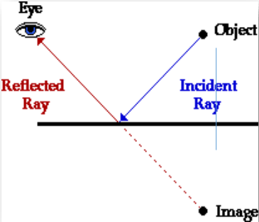
Angle of incidence – angle between incident ray and normal
Angle of reflection – angle between reflected ray and normal
Angle of incidence equals angle of reflection.

Example 1. According to the law of reflection, angle of incidence is equal to the angle of reflection so in the example given above, angle of reflection = 31 degrees as well.

Example 2. A light ray strikes a reflective plane surface at an angle of 56° with the surface.
a) Find the angle of incidence.
b) Find the angle of reflection.
c) Find the angle made by the reflected ray and the surface.
d) Find the angle made by the incident and reflected rays.
Summarization:
Reflection is the bouncing back of light into the original medium where it has been traveling after striking a surface.
Reflection from smooth surfaces is called regular reflection while reflection from rough surfaces is called diffuse reflection.
The laws of reflection are the following:
a**.) the angle of incidence is equal to the angle of reflection**
b.) incident ray, reflected ray and the normal line all lie on one plane.
MIRRORS
Mirror - is any surface that is smooth enough to produce regular reflection of light incident on it.
Types of Mirrors
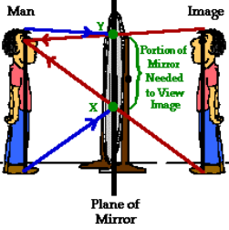
Plane Mirror – flat surfaced mirrors. Images on plane mirrors are virtual, upright, same size as the object, same distance behind the mirror as the object in front of the mirror and laterally reversed.
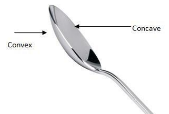
Spherical or Curved Mirror - have reflecting surfaces taken from the surface of a sphere. It can be a concave or convex spherical mirror.
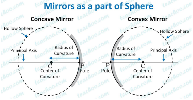
The center of curvature C is the center of the sphere from where the mirror was taken.
The vertex V is the center of the mirror also known as the pole of the mirror
The radius of the curvature R is the radius of the sphere. it is the distance between C and V
Principal axis or optical axis is the straight line connecting C and V
Aperture refers to the width of the mirror
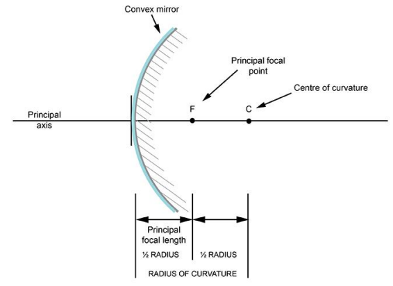
The principal focus F is the intersection of the reflected rays.
The focal length f is the distance from V to F. Half of R.
Magnification – the size of the image relative to the size of the object.
Summarization:
Mirrors are any smooth reflecting surfaces: plane or spherical.
Images formed by plane mirrors are always virtual, upright and same size as the object and will be reflected at the same distance behind the mirror.
Spherical mirrors can be concave or convex. Concave mirrors are converging mirrors while convex mirrors are diverging mirrors.
Electromagnetic Waves & the Electromagnetic Spectrum
Electromagnetic waves (EM waves)
are transverse waves without a medium.
They can travel through empty space.
They travel as vibrations in electrical and magnetic fields.

EM waves are described using:
Frequency (f) is the number of cycles that a wave makes per unit of time and is usually expressed in units of Hertz (Hz) or 1/s (per second).
Amplitude is the distance from the equilibrium point (x-axis) of a propagating wave to the highest or lowest point of the waveform.
Wavelength (λ) is the distance between identical points in successive cycles in a propagating wave and is usually in nanometers (nm) for the visible light region.
James Clerk Maxwell - father of electromagnetic theory: Maxwell’s Equations
Heinrich Hertz – discovery of the electromagnetic waves other than light
Electromagnetic Spectrum - name for the range of electromagnetic waves when placed in order of increasing frequency.

The EM spectrum consists of EM waves arranged from the longest to shortest wavelength (from left to right) and lowest to highest frequency from left going right:
Radio waves – longest wavelength and lowest frequency Applications: Global Positioning Systems (GPS), RADAR (RAdio Detection And Ranging), Magnetic Resonance Imaging (MRI)
Micro waves – discovered by James Maxwell Applications: Microwave oven, microwave ablation
Infrared – infrared means ‘below red’. Shorter wavelength and higher frequency than microwaves. Discovered by William Herschel. The human body gives off infrared rays Applications: shawarma machines, TV remote controls, other electric appliances
Visible light – the only EM wave visible to the naked eye. Longest wavelength in the color spectrum is red light. Shortest wavelength is violet (purple) light. Application: LEDs, Light Amplification by Stimulated Emission of Radiation (LASER), imaging, surgery, endoscopy, microscopy, etc.
Incandescence VS Luminescence Incandescence – emission of light object is heated to a high temperature. Example is burning wood and charcoal, electric bulb. Luminescence – light emission without a significant change in temperature.
Example is bioluminescence: fireflies and worms
UV rays - Carry more energy than visible light. Wilhelm Ritter was creadited for its discovery. Application: Sterilization of medical equipment, vitamin D production from UV rays of sun
X-rays or Roentgen rays – also known as roentgen rays after its discoverer Wilhelm Conrad Roentgen. Bones and teeth absorb x-rays but too much exposure can lead to cancer. Application: Engineers use x-rays to check for tiny cracks in structures
Gamma rays - Carry the greatest amount of energy and penetrate the most. Paul Villard is credited for its discovery. Application: treatments for cancer cells, used in nuclear weapons.
Summarization:
Electromagnetic waves or electromagnetic radiations are produced by accelerating charges.
EM waves are transverse waves that can travel in a vacuum and in a material medium and they move at 3 x 10⁸ m/s.
The Electromagnetic spectrum is the arrangement of EM waves in order of decreasing wavelengths or increasing frequency. The different types of EM waves are radio waves, microwaves, infrared rays, visible light, ultraviolet rays, x-rays and gamma rays.