

5 & 6 X-Ray Contrast, Radiation Dose, & Image Artifacts
Intro
All photons impart energy to the object
All photons deliver a dose of energy
As photons interact with matter, they are absorbed, scattered, or transmitted
Exposure: The amount if radiation in air measured by radiation monitors
Exposure is measured in roentgen (R) and coulomb/kg
Absorbed dose: The dose of radiation (energy) you are delivering to the tissue, measured by the energy absorbed
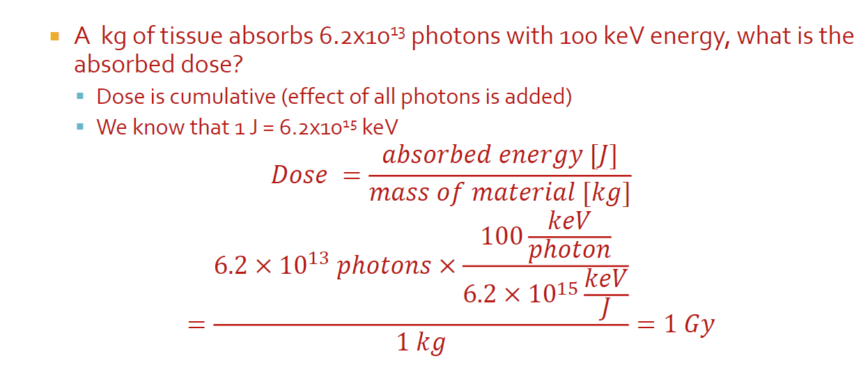
The absorbed dose is measured in units of gray (Gy)
1 Gy = 1 J absorbed by 1kg of tissue
Used to be rad (radiation absorbed dose) which is 0.01 Gy
Math
1 J = 6.2 x 10^15 keV
All can be done with just units
Biological Effect of Dose
Risk to different tissue is dependant on tissue type and the type of radiation
Dose equivalent: A measure of the biological damage to living tissue as a result of the absorbed dose; the biological dose that delivers the same degree of risk to a tissue regardless of the radiation type
Dose equivalent is measured in Severt (Sv) which is Gy times quality factor (f)
Usually in mSV (small numbers)
Effective dose: An estimate ofo the stochastic effect that a non-uniform radiation dose has on the whole body; weighted sum of dose equivalent by all organs
Sum of each organ: weighting factor times (absorbed dose of the organ times f)
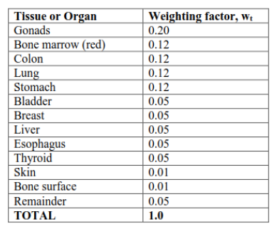
Image Contrast
Contrast: The difference between foreground and background on an image
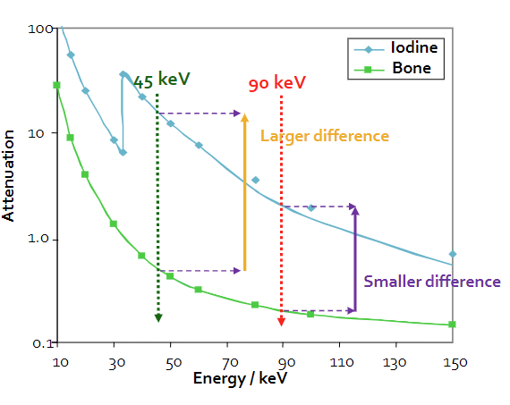
In x-rays, contrast represents the difference in attenuation properties (μ) of materials along a path
When μ increases, image brightness increases
When the change in μ increases, image contrast increases
Generally, μ decreases with energy, but it depends on the material
Iodine injections have a higher attenuation coefficient and are used to increase contrast in imaging
Increasing the energy decreases the change in attenuation coefficient, which can also be used to improve contrast (so that more particles hit your receptor)
Beam Intensity
Beam intensity: The rate of change of the number of photons per unit area, represented by I
I = (number photons/area)/change in time
I(x) = I0 * e^-μx
We will use “I” (intensity) interchangeably with “N” (number of photons), especially as a relative measure, however, keep in mind that they are representing different things
Beams are polychromatic or polyenergetic (can be used interchangably)
Spectrum Effective Energy
Effective energy is the weighted average of the spectrum energies (needed because x-rays are polychromatic)
Because effective energy is different for different materials, we pick the μ that has the biggest difference between materials
Filters: Something used to reshape the radiation spectrum to eliminate energies that don’t contribute to the image, but do deliver dose
Removing photons from the spectrum depends on their energy, the filter material, and the filter’s path length
For math, remember you cannot use the same μ for different energies
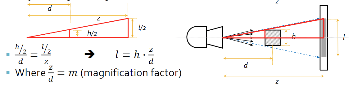
System & Beam Geometry
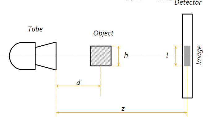
Source-object distance (SOD): How far is the sample from the source?
Source-image distance (SID): How far is the source from the detector image?
Object size (h)
Image size (l)
Magnification factor: How much larger is the image from the actual sample?
Parallel beam geometry is the ideal geometry, stating that all the beams move parallel to one another
Parallel beam geometry has some limitations, because the source size must be as large as the largest object imaged, it’s inconsisent with particle physics, and complex
Parallel beam geometry suggests simple math and no need to calculate the true size of the object from the image
No magnification effect from a parallel beam
Fan (divergent) beam geometry (non-ideal) suggests that the beams come out from the source in a cone-like shape
Fan beam geometry have a more compact, practical design, and is more consistent with physics
Fan beam geometry requires magnification factor to be taken into account, as well as depth dependent magnification (objects must be the same distance from tube)
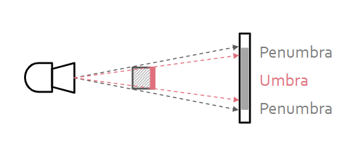
To reduce the radiation sent to parts of the body that we don’t want to image, we use a tube-side collimator, which focuses beam on the center of the object, making the beams closer to parallel
To reduce non-parallel beams and scattered photons, we use a detector-side collimator, or more commonly a radiographic grid, to absorb any scattered photons that are trying to reach the detector that would otherwise create noise