


CURRENT ELECTRICITY
Define electric current and write its equation?
Electric current is the flow of electric charge in a conductor. It is the rate of flow of electric charge through a cross-section of a conductor, measured in amperes (A).
The equation for electric current is:
I = Q/t
Where:
I is the electric current in amperes (A)
Q is the electric charge in coulombs (C)
t is the time in seconds (s)
This equation shows that electric current is directly proportional to the amount of electric charge that flows through a conductor in a given time. In other words, the larger the amount of electric charge that flows through a conductor in a given time, the greater the electric current.

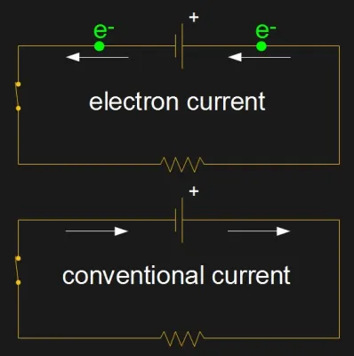
What do you mean by Conventional current ?
Conventional current is a theoretical model used to describe the direction of flow of electric current in a circuit. According to this model, current flows from the positive terminal of a voltage source, such as a battery, to the negative terminal. This is the opposite of the actual flow of electrons, which move from the negative terminal to the positive terminal.
The use of conventional current is a historical convention, dating back to the early days of electrical science, when it was not yet understood that electrons were the charge carriers in conductors. At that time, the direction of current flow was defined as the direction of flow of a hypothetical fluid called "conventional current", which was thought to flow from positive to negative.
Today, we know that electrons are the charge carriers in conductors, and the actual flow of current is from negative to positive. However, the convention of using conventional current is still widely used in circuit analysis and design, and it is important to understand this convention when working with electrical circuits.
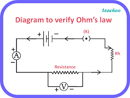
State and explain Ohm's law ?
Ohm's law is a fundamental law of electricity that relates the electric current flowing through a conductor to the voltage applied across it and the resistance of the conductor. The law states that:
The current flowing through a conductor is directly proportional to the voltage applied across it, and inversely proportional to the resistance of the conductor.
In equation form, Ohm's law can be expressed as:
I = V/R
Where:
I is the current flowing through the conductor, measured in amperes (A)
V is the voltage applied across the conductor, measured in volts (V)
R is the resistance of the conductor, measured in ohms (Ω)
This means that if the voltage applied across a conductor is increased, the current flowing through it will also increase, as long as the resistance of the conductor remains constant. Similarly, if the resistance of the conductor is increased, the current flowing through it will decrease, as long as the voltage remains constant.
Ohm's law can also be used to calculate the voltage or resistance of a conductor, given the other two values. For example, if the current and resistance of a conductor are known, the voltage can be calculated using V = IR. Or if the voltage and current are known, the resistance can be calculated using R = V/I.
Overall, Ohm's law is a fundamental tool for understanding and designing electrical circuits, and is essential knowledge for anyone working with electronics.
What is Unit of current?
The unit of electric current is the ampere (A), which is defined as the flow of electric charge across a conductor at a rate of one coulomb per second. In other words, an electric current of one ampere means that one coulomb of electric charge is flowing through a conductor in one second.
The ampere is a base unit in the International System of Units (SI), and is used to measure the flow of electric current in a wide range of applications, from household electronics to industrial power systems. Other common units of current include the milliampere (mA), which is one-thousandth of an ampere, and the microampere (μA), which is one-millionth of an ampere.
Explain the Volt ?
Volt is the unit of measurement for electric potential difference or electric voltage. It is a measure of the amount of electrical energy that is transferred or transformed in an electrical circuit per unit of electric charge.
The volt is defined as the potential difference between two points in a circuit when one joule of electrical energy is used to move one coulomb of charge between those two points. In equation form, this can be expressed as:
1 volt = 1 joule / 1 coulomb
The volt is named after the Italian physicist Alessandro Volta, who invented the first electric battery. It is a base unit in the International System of Units (SI) and is used to measure the voltage of batteries, electrical outlets, and other electrical systems. Voltages can range from a few volts in small electronic devices to thousands of volts in high-voltage power transmission systems.
What is Switch ?
A switch is an electrical device that is used to control the flow of electric current in a circuit by opening or closing the circuit. It is a simple and common component in electrical and electronic circuits, and can be used to turn devices on or off, or to control the direction or speed of a motor, for example.
A switch typically consists of two or more metal contacts that are designed to touch or separate when the switch is turned on or off. When the contacts are touching, the switch is closed and the circuit is complete, allowing electric current to flow through the circuit. When the contacts are separated, the switch is open and the circuit is broken, preventing electric current from flowing through the circuit.
Switches can be operated manually, such as a light switch that is turned on or off by flipping a lever, or they can be operated automatically, such as a temperature switch that is triggered by changes in temperature. Switches can also be classified according to their design, such as toggle switches, push-button switches, rocker switches, rotary switches, and slide switches, among others.
Overall, switches are essential components in many electrical and electronic circuits, and are used to control the flow of current in a variety of applications.
What is Resistance ?
Resistance is the property of a material or a component that opposes the flow of electric current through it. It is measured in units of ohms (Ω) and is represented by the symbol "R".
The resistance of a material or component is determined by its composition, geometry, and other factors. For example, materials with high resistivity, such as ceramics and insulators, have high resistance to the flow of current, while materials with low resistivity, such as metals, have low resistance. Similarly, longer and thinner conductors have higher resistance than shorter and thicker conductors.
Resistance can also be affected by temperature, as the resistance of most materials increases with temperature. This is known as positive temperature coefficient of resistance.
The relationship between voltage, current, and resistance is described by Ohm's law, which states that the current through a conductor is directly proportional to the voltage applied across it and inversely proportional to its resistance. This means that as the resistance of a material or component increases, the current flowing through it decreases, for a given voltage.
Resistance plays a critical role in the design and analysis of electrical and electronic circuits, and is used in a wide range of applications, from power transmission and distribution to electronic devices and control systems.
What is Earthing and safety ?
Earthing, also known as grounding, is the process of connecting an electrical device or system to the Earth through a conductor or wire. The purpose of earthing is to provide a path for electrical current to flow to the Earth in case of a fault or short circuit, which helps to prevent electric shocks, fires, and other safety hazards.
Earthing is an important safety measure in electrical systems, as it helps to protect people and equipment from electrical faults and lightning strikes. When a fault occurs in an electrical system, such as a short circuit or overvoltage, the earthing system provides a low-resistance path for the electrical current to flow to the Earth, which helps to prevent damage to equipment and reduces the risk of electric shock or fire.
In addition to protecting against faults, earthing is also used to protect against lightning strikes. Lightning can induce high voltages in electrical systems, which can damage equipment and create safety hazards. By providing a path to the Earth, earthing helps to dissipate the electrical energy from lightning strikes and reduce the risk of damage or injury.
Overall, earthing is a critical safety measure in electrical systems, and is required by electrical codes and standards in many countries. Earthing systems typically consist of a grounding electrode, such as a metal rod or plate, that is buried in the Earth, and a grounding conductor or wire that connects the electrode to the electrical system. Proper design, installation, and maintenance of earthing systems is essential for ensuring the safety and reliability of electrical systems.
