


Unit 5 : Magnetism and Electromagnetic Induction
Magnetic Field:
The space surrounding a magnet is called magnetic field.
The direction is defined as pointing out of the north end of a magnet and into the south end of a magnet.

To visualise the magnetic field we use magnetic field lines.
Magnetic field lines emanate from or enters in the surface of a magnetic material at any angle.
Magnetic field lines exist inside every magnetised material.
Magnetic field lines can be mapped by using iron dust or using compass needle.
We use (x) when the magnetic field goes into the plane.
We use (.) when the magnetic field goes out of the plane.
There are no monopoles as they always exist in pairs.
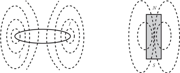
Bar Magnets:
A permanent bar magnet creates a magnetic field that closely resembles the magnetic field produced by a circular loop of current-carrying wire.
The magnetic field created by a permanent bar magnet is due to the electrons.
All materials have some magnetic permeability which determines how great a magnetic field an object will develop.
Magnetic poles repel each other when they are the same and opposite poles attract each other.

The magnetic force on a moving charge:
If a particle with charge q moves with velocity v through a magnetic field B, it will experience a magnetic force, Fb:
With magnitude:
If angle = 90 degrees, it is the max value.
0 or 180, velocity and magnetic field are parallel or antiparallel, here the magnetic force is zero.
Right-Hand Rule:
Whenever you use the right-hand rule, follow these steps:
1. Orient your hand so that your thumb points in the direction of the velocity v. If the charge is negative, turn your thumb by 180 degrees.
2. Point your fingers in the direction of B.
3. The direction of FB will then be perpendicular to your palm.

Example 1: For each of the following charged particles moving through a magnetic field, determine the direction of the force acting on the charge.

Solution:
If you point your fingers to the top of the page and thumb to the right of the page, your palm should point out of the page. The force is out of the page.
If you point your fingers into the page and thumb to the top of the page, your palm should point to the left of the page. The force is to the left of the page.
If you point your fingers into the page and thumb to the right of the page (remember, when the charge is negative, your thumb points in the opposite direction from the velocity), your palm should point to the bottom of the page. The force of a positive charge would be toward the bottom of the page, but because this is a negative charge, the force points up.
Example 2: A charge +q = +6 × 10⁻⁶ C moves with speed v = 4 × 10⁵ m/s through a magnetic field of strength B = 0.4 T, as shown in the figure below. What is the magnetic force experienced by q?

Solution: the magnitude of is . By the right hand rule, the direction is into the plane of the page, which is symbolized by x.
The magnetic force on a current-carrying wire:
Let a wire of length l be immersed in magnetic field B. I the wire carries current I, then the force on the wire is,
With magnitude:
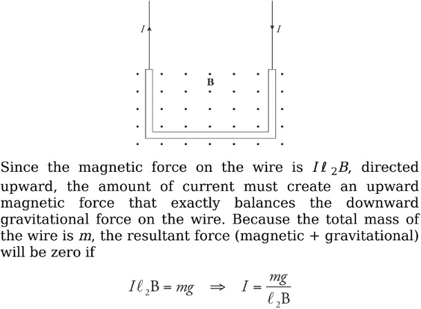
Example: A U-shaped wire of mass m is lowered into a magnetic field B that points out of the plane of the page. How much current I must pass through the wire in order to cause the net force on the wire to be zero?
Solution. The total magnetic force on the wire is equal to the sum of the magnetic forces on each of the three sections of wire. The force on the first section (the right, vertical one), FB1, is directed to the left (applying the righthand rule, and the force on the third piece (the left, vertical one), FB3, is directed to the right. Since these pieces are the same length, these two oppositely directed forces have the same magnitude, Il 1B = Il 3B, and they cancel. So the net magnetic force on the wire is the magnetic force on the middle piece. Since I points to the left and B is out of the page, the right-hand rule tells us the force is upward.
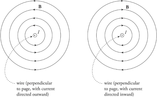
Magnetic fields created by current-carrying wire:
Magnetic fields are unending loops.
The direction of the circles is determined by the right-hand rule.
is the permeability of free space.
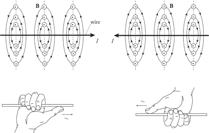
Right-hand rule for the magnetic field created by a current-carrying wire:
1. Put your thumb in direction of current or in direction of a positive traveling charge.
2. Grab the wire/path.
3. As the fingers curl around your thumb, it represents the magnetic field going around the wire/path.
Example: The diagram below shows a proton moving with a speed of , initially parallel to, and 4 cm from, a long, straight wire. If the current in the wire is 20 A, what’s the magnetic force on the proton?
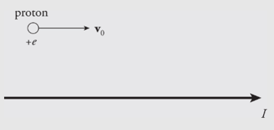
Solution. Above the wire (where the proton is), the magnetic field lines generated by the current-carrying wire point out of the plane of the page, so points downward. Since the proton’s charge is positive, the magnetic force is also directed down, toward the wire.

Solenoids create uniform fields:
Magnetic fields are unending loops.
Solenoid is a device that is constructed by a series of coaxial wires through which a continuous current flows.
Solenoid is an electromagnet.
The field inside a solenoid inside a laboratory is very uniform in both direction and strength.
When there is no current, there is no magnetic field.
Motional EMF:
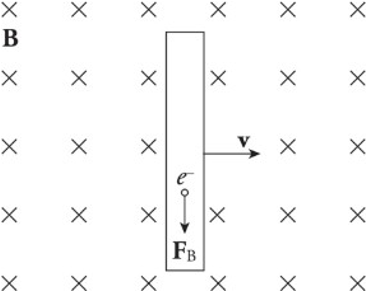
The simple act of moving a conducting rod in the presence of an external magnetic field that creates an electric field within the rod.
The presence of a moving conductor inside the magnetic field results in the creation of an electric field that points in the same direction as the magnetic force on the electrons.
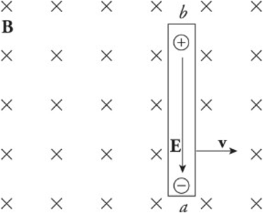
The figure shows a conducting wire of length l moving with constant velocity v in the plane through a uniform magnetic field perpendicular to the page. This induced electric field points downward.
As long as the rod continues to move at velocity v, the electric field will be maintained within the rod.
A charge q in the wire feels two forces:
Electric force:
Magnetic force: (sin 90 degrees = 1)
If q is negative, Fe is upward and Fb is downward.
If q is positive, Fe is downward and Fb is upward.
Once the magnitude of Fe equals the magnitude of Fb, the charges in the wire are in electromagnetic equilibrium.
The presence of the electric field requires a potential difference between the ends of the rod. The potential difference Vba is equal to Eℓ and, since E = vB, the potential difference can be written as vBℓ.
Induced Current:
An induced current is created in three ways:
Changing the area of the loop of wire in a stationary magnetic field.
Changing the magnetic field strength through a stationary circuit.
Changing the angle between the magnetic field and the wire loop.
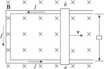
Each of these changes causes a change in flux. The motion of a sliding rod through the magnetic field creates an electromotive force, called motional emf.
An external agent must provide this same amount of force to the right to maintain the rod’s constant velocity.
The power that the external agent must supply is , and the electrical power delivered to the circuit is .
The two expressions are identical as the energy provided by the external agent is transformed first into electrical energy and then thermal energy as the conductors making up the circuit dissipates heat.
The relationship between current in a coil of wire and magnetic fields sets the basis for Faraday’s Law.
Faraday’s Law of Electromagnetic Induction:
Electromotive force can be created by the motion of a conducting wire through a magnetic field.
A current is induced when the magnetic flux passing through the coil or loop of wire changes.
Magnetic flux helps us define what the amount of field passing into the loop means.
Imagine holding a loop of wire in front of a fan as shown:
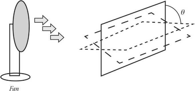
The amount of air that flows through the loop depends on the area of the loop as well as its orientation (tilt angle θ).
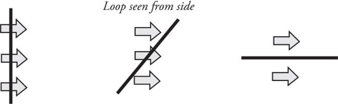
The most effective airflow is when the loop is completely perpendicular, as in the situation to the left. The least effective is when the airflow and loop are in the situation to the right.
Example 1: The figure below shows two views of a circular loop of radius 3 cm placed within a uniform magnetic field, B (magnitude 0.2 T). (a) What’s the magnetic flux through the loop? (b) What would be the magnetic flux through the loop if the loop were rotated 45°? (c) What would be the magnetic flux through the loop if the loop were rotated 90°?
Solution:

According to Faraday’s Law of electromagnetic radiation, the magnitude of the emf induced in a circuit is equal to the rate of change of the magnetic flux through the circuit. This can be written mathematically in the form
Lenz’s Law: The induced current will always flow in the direction that opposes the change in magnetic flux that produced it.
It can be included mathematically with Faraday’s law of electromagnetic radiation of a minus sign:
Example 2: The circular loop of Example 1 rotates at a constant angular speed through 45° in 0.5 s. (a) What’s the induced emf in the loop? (b) In which direction will current be induced to flow?

Solution: The current will flow only while the loop rotates, because emf is induced only when magnetic flux is changing. If the loop rotates 45° and then stops, the current will disappear.
