


Lesson 1 (copy)
LESSON 1: INTRODUCTION TO PLUMBING
PLUMBING
The art and technique of installing pipes, fixtures, and other apparatuses in buildings for bringing in the supply, liquids, substances and/or ingredients and removing them; and such water, liquid, and other carried wastes hazardous to health, sanitation, life, property; also, the pipes and fixtures after installations i.e., the plumbing system.
HISTORY OF PLUMBING
Ancient Plumbing System (2600 BC)
The very first system of pipes to carry water from one place to another was built in the Indus Valley Civilization. Buildings here had wells and bathing areas with drains in the floors. They had bathrooms with septic tanks, very similar to modern-day bathrooms.
Advent of Pipelines (2000 BC)
By this time, in places like China, hollow bamboo reeds were used as pipes to carry fresh water and natural gas to and from the ancient salt mines.
Plumbing in Egyptian, Greek, Roman Civilizations (1500 BC)
On the island of Crete, Minoan Kings had bathrooms with hot and cold running water. The Minoan Palace of Knossos used ceramic bathtubs along with the world’s first flushing toilet complete with drainage systems.
The earliest plumbing pipe was made of baked clay and straw while the Egyptians made the first copper pipes. The Egyptian plumbing process was as formidable as their building expertise. In their search for water, Egyptians dug wells as deep as 300 feet, and the water wheel was born here.
The Greeks advanced the art and science of plumbing. Hot and cold running water and bathtubs were part of everyday life in ancient Greece. The Greeks pioneered shower technology for athletes to bathe after the Olympic games where water moved through overhead pipes and came out through sculpted shower heads.
But the most magnificent accomplishments in plumbing were those of the Romans. More than 1000 years ago, the Romans built water channels that carried water from the mountains into the city, which distributed it through underground supply lines made of lead. That is where the term ‘Plumbing’ originated, as ‘Plumus’ in Latin means Lead.
Public latrines had 20 seats or more arranged in a circular manner, where water constantly ran beneath them, to carry the waste into the nearest sewer
Water Systems in Babylon (600 BC)
Under King Nebuchadnezzar II, Babylon had become the most magnificent city of ancient times. His palace had separate bathrooms with elaborate drains as well as latrines with raised seats, connected to a covered sewer system.
Inventor of First Flushable Toilet: John Harington (1596)
Queen Elizabeth I’s godson, John Harington invented the first flush toilet for the Queen at her residence at Richmond Palace.
Water Works (1600)
The concept of the shower began in ancient times with outdoor waterfalls and buckets of water. The first water system in America was built in Boston in the mid-1600s.
The French Connection (1664)
King Louis XIV of France ordered the construction of main plumbing lines made of cast – iron.
Alexander Cumming patents the Flush Toilet (1775)
The first valve - type flush toilet was introduced in 1738 by a man named J.F. Brondel. Also in the year 1775, Alexander Cumming, a Scottish watchmaker, and inventor became the first Englishman to patent design of the flush toilet
Joseph Bramah’s WC (1778)
Joseph Bramah improvised Cumming’s invention using hinged valves. His creation is the prototype for closets aboard ships and boats.
New York City Gets its Firefighting Water System (1795)
In 1795, wooden pipelines were built to carry water for firefighting using hollow logs of wood. The firemen had to drill through the walls of these pipes and after they finished, plug the hole. This is how the term ‘fireplug’ originated.
The First Shower Invented (1810)
One of the earliest modern-style showers was the English Regency Shower that pumped water continually from a lower basin to a cistern directly above the bather’s head using the same wastewater.
Water Systems in Philadelphia (1815)
The city of Philadelphia was among the first to undertake a safe water supply as a governance issue. Water pipelines ran throughout the length and breadth of the city supplying both paid and free supply.
PLUMBING SYSTEM
Includes all potable water supply and distribution pipes, all plumbing fixtures, and traps; all sanitary and storm drainage systems; vent pipes, roof drains, leaders, and downspouts; and all building drains and sewers, including their respective joints and connections; devices, receptacles, and appurtenances within the property; water lines in the premises; potable, tap, hot and chilled water piping’s; potable water treating or using equipment; fuel gas piping; water heaters and vents for same.
MAJOR COMPONENTS OF A PLUMBING SYSTEM
Plumbing Fixtures
The receptacles that receive the supplied water and allow the building occupants to avail and use the water.
Drainage, Waste and Vent (DWV)
The piping network within the building which conveys from the plumbing fixtures all wastes and rainwater to a treatment facility and point of disposal.
Water Supply & Distribution System
Carries water from the water source, street main or a pump to the building and to various points of use.
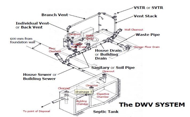
The Drainage System or DWV System
It includes all the piping’s within public or private premises which conveys sewage or other liquid wastes to a legal point of disposal but does not include the mains of a public sewer system or a public sewage treatment or disposal plant.
Sanitary/Soil Drainage
Waste Drainage
Storm Drainage
Vent System
WATER SUPPLY AND DISTRIBUTION SYSTEM
The Domestic Cold - Water Supply of the plumbing system consists of the piping and fittings which supply cold water from the building water supply to the fixtures, such as lavatories, bathtubs, water closets and kitchen sinks.
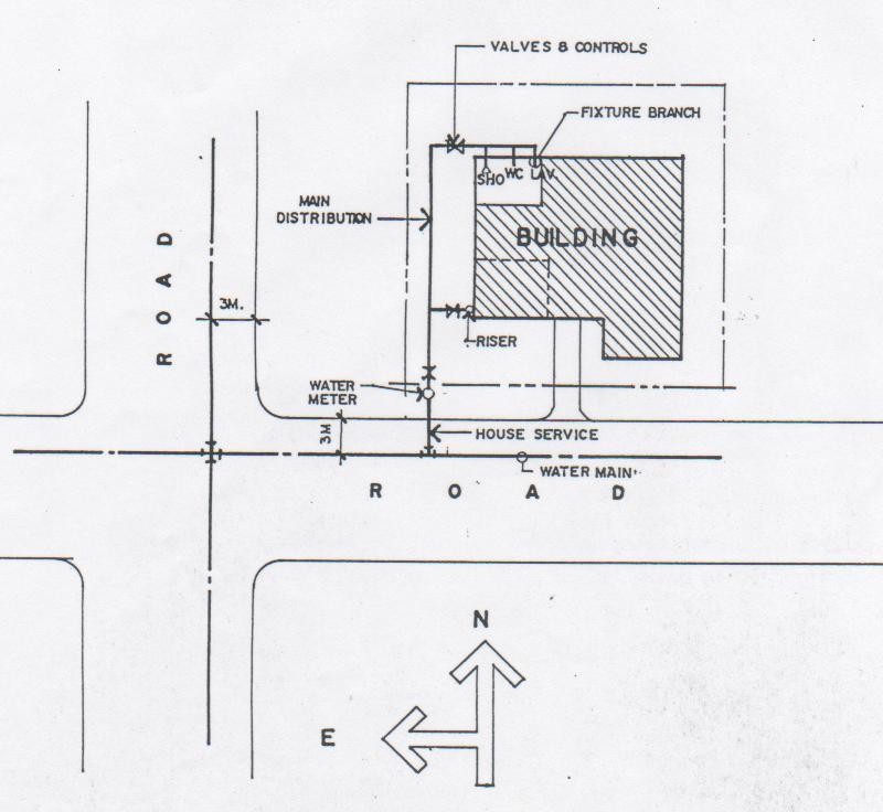
Elements of the Water Supply and Distribution System
Water Service or House Service
Water Meter
Distribution Main or Horizontal Supply Main
Fixture Branches
Riser
Valves and Control
Storage Tanks
Elements of the Domestic Distribution System
Water (Street) Main
A water supply pipe for public or community use controlled by public authority.
Water – Service Pipe
The pipe from the water main, water meter, water supply system or other approved source of water supply, to the building or structure served.
Water – Distribution Pipe
A pipe which conveys potable water from the building supply pipe to the plumbing fixtures & other water outlets in the building.
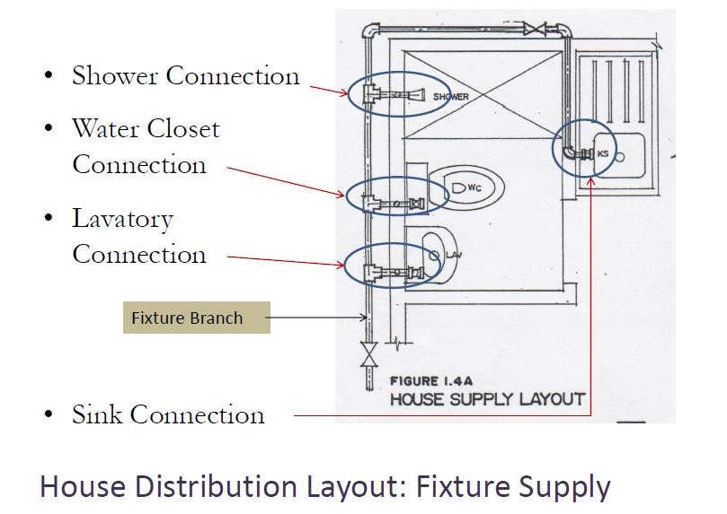
Fixture Branch
A pipe connecting several fixtures.
Fixture Supply
A water supply pipe connecting the fixture with the fixture branch or directly to a main water supply pipe.
LESSON 2: BASIC PRINCIPLES OF PLUMBING
PLUMBER is the one who works or engages in the business of installing in buildings the pipes, fixtures, and other apparatus for bringing in the water supply and removing liquid and waterborne wastes.
CATEGORIES OF PLUMBER
Apprentice Plumber – a beginner at the trade who usually serves for 3 to 5 years as a helper to a journeyman.
Journeyman Plumber – has served his apprenticeship and is competent to perform the tasks of installing and repairing the plumbing system.
Master Plumber – a person technically and legally qualified and licensed to practice the profession of master plumbing without limitations in accordance with R.A. 1378, having passed the examinations conducted by the Professional Regulation Commission, has received a Certificate of Registration from the Board of Master Plumbing, and possesses the current License to Practice.
THE PLUMBING CODE
The Plumbing Code is the manifestation of the right of the government to regulate the practice of the plumbing profession based on the principle of the protection of public health.
The basic goal of the National Plumbing Code of the Philippines is to ensure the qualified observance of the latest provisions of the plumbing and environmental laws.
BASIC PRINCIPLES OF THE 1999 NATIONAL PLUMBING CODE OF THE PHILIPPINES
All premises intended for human habitation, occupancy or use shall be provided with a supply of pure and wholesome water, neither connected with unsafe supplies nor subject to hazards of backflow or back siphonage.
Plumbing fixtures, devices and appurtenances shall be supplied with water in sufficient volume and at a pressure adequate to enable them to function satisfactorily and without undue noise under normal conditions of use.
Plumbing shall be designed and adjusted to use the minimum quantity of water consistent with proper performance and cleaning.
Devices for heating and storing water shall be so designed and installed as to prevent dangers from explosion through overheating.
Every building having plumbing fixtures installed and intended for human habitation, occupancy or use on premises abutting on a street, alley, or easement where there is a public sewer, shall be connected to the public sewer system.
Each family dwelling unit on premises abutting on a sewer or with a private sewage disposal system shall have at least 1 water closet and 1 kitchen - type sink. Further, a lavatory or bathtub or shower shall be installed to meet the basic requirement of sanitation and personal hygiene.
Plumbing fixtures shall be made of smooth non- absorbent material, free from concealed fouling surfaces and shall be in ventilated enclosures.
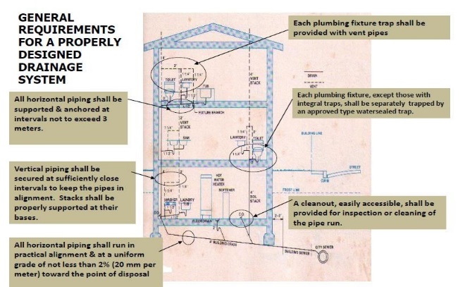
The drainage system shall be designed, constructed, and maintained to safeguard against fouling, deposit of solids, clogging and with adequate cleanouts so arranged that the pipes might be readily cleaned.
All piping of plumbing systems shall be of durable NAMPAP – APPROVED materials, free from defective workmanship, designed and constructed by Registered Master Plumbers to ensure satisfactory service.
Each fixture directly connected to the drainage system shall be equipped with water – sealed trap.
The drainage piping system shall be designed to provide adequate circulation of free air from siphonage, aspiration or forcing of trap seals under ordinary use.
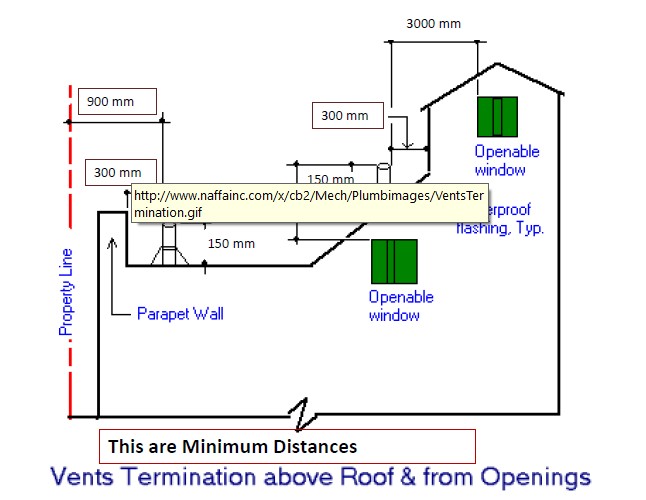
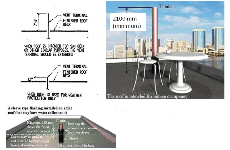
Vent terminals shall extend to the outer air and installed to preempt clogging and the return of foul air to the building.
Plumbing systems shall be subjected to such tests to effectively disclose all leaks and defects in the workmanship.
No substance which will clog the pipes, produce explosive mixtures, destroy the pipes or their joints or interfere unduly with the sewage disposal process shall be allowed to enter the building drainage system.
Proper protection shall be provided to prevent contamination of food, water, sterile goods & similar materials by backflow of sewage. When necessary, the fixture, device or appliance shall be connected indirectly with the building drainage system.
No water closet shall be in a room or compartment which is not properly lighted or ventilated.
If water closets or other plumbing fixtures are installed in buildings where there is no sewer within a reasonable distance, suitable provision shall be made for disposing of the building sewage by some accepted method of sewage treatment and disposal, such as septic tank.
Where a plumbing drainage system may be subject to backflow of sewage, suitable provision shall be made to prevent its overflow in the building.
Plumbing systems shall be maintained in serviceable condition by Registered Master Plumber.
All plumbing fixtures shall be properly spaced, to be accessible for their intended use.
Plumbing shall be installed by Registered Master Plumbers with due regard to the preservation of the strength of structural members and the prevention of damage to walls and other surfaces through fixture usage.
LESSON 3: PLUMBING FIXTURES (PART 1)
Plumbing Fixtures are approved – type installed receptacles, devices or appliances supplied with water or liquid – borne wastes and discharge such wastes into the drainage system to which they may be directly or indirectly connected. Industrial or commercial tanks, vats, and similar processing equipment are not plumbing fixtures, but may be connected to or discharge into approved traps or plumbing fixtures as approved for in this Code. (Sec. 217.10 NPC 1999)
COMMON TYPES OF PLUMBING FIXTURES
Water Closet
Bathtub/ Shower
Bidet
Lavatory
Kitchen Sink
Urinal
WATER CLOSET
Water closet is a plumbing fixture used to receive human excrement and to discharge it through a waste pipe, using water as a conveying medium.
CLASSIFICATION OF WATER CLOSETS
Design
Make
Flushing Mechanism Used
Shape
Installation
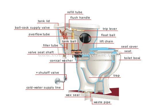
PARTS OF A WATER CLOSET
WATER CLOSET AS TO DESIGN
Siphon Washdown – it is the least expensive but the noisiest. Only small amount of standing water, susceptible to fouling, staining and contamination.
Siphon Jet – the jet being submerged, introduces water underwater so that its operation is entirely muffled. It has a large amount of standing water to prevent fouling.
Siphon Vortex – this type of bowl develops its flushing action through the water entering the diagonal holes around the rim which creates a swirling action which forms a vortex in.
Reverse Trap – the trap way located at there are eliminated the bulge at the front. The design of the bowl plus its large water area and quietness in operation, makes it desirable than the siphon washdown.
WATER CLOSET AS TO MAKE
One – piece – the water closet fixture is manufactured with the bowl and the flush tank molded into a single unit.
Close Coupled – a water closet wherein the flush tank is separate but is attached to the toilet bowl. It is a two – piece model.
Pail Flush – a water closet comprising only of a bowl without a flush tank. Flushing action is obtained only through water poured from a pail or bucket. This is used in areas where running water system is not available.
Squat Bowl
WATER CLOSET AS TO SHAPE
Round front
Elongated front
WATER CLOSET AS TO INSTALLATION
Free standing or floor mounted
Wall hung or wall mounted
LAVATORY
A lavatory is a fixture designed for the washing of the hands or face. It is also known as a Wash Basin.
TYPES OF LAVATORIES
Wall Hung Lavatory
Pedestal Lavatory
Counter – Type Lavatory
Over counter Lavatory
Counter Type Lavatory
Over counter or Countertop
Undercounter
One – piece Lavatory
BATHTUB
A bathtub is a tub for bathing, usually a fixed plumbing installation designed for 1 person. It is available in left outlet and right outlet.
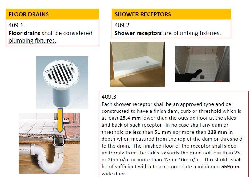
SHOWER BATH
A shower bath is an apparatus for spraying water on the body, usually from above. Drain is through the shower bath floor drain.
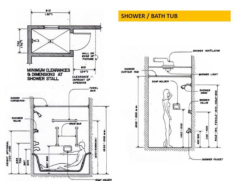
SHOWER COMPARTMENT
Sec. 409.4
All shower compartments, regardless of shape, shall have a minimum finished interior area of 0.60 square meter, and shall also be capable of encompassing a 762mm diameter circle. The minimum area and dimension shall be maintained from a point above the shower drain outlet to a height of 1.78m with no protrusions other than the fixture valve or valves, shower head and safety grab bars or rails.
KITCHEN SINK
A kitchen sink is a plumbing fixture consisting of a basin with a water supply, connected with a drain and used for dishwashing.
BIDET
A bidet is a plumbing fixture used for used for washing the middle part of the body, especially the genitals. It is also known as Sitz Bath.
URINAL
A urinal is a plumbing fixture equipped with a water supply and drain for flushing away urine.
TYPE OF URINAL
Wall Hung Urinal
Pedestal Urinal
Stall Urinal
Trough Urinal
Female Urinal
OTHER TYPES OF PLUMBING FIXTURES
Slop Sink – a deep sink, set low and used by janitors for emptying pails of dirty water and mop cleaning.
Laundry Tub – a deep wide sink used for washing clothes.
Scrub Sink – is a plumbing fixture usually located in the operating room in a hospital to enable personnel to scrub their hands prior to a surgical procedure.
Hot and Cold – Water Supply – is activated by a knee – action mixing valve or by wrist or pedal control or by automatic sensors.
Drinking Foundation – is a plumbing fixture consisting of a shallow basin, together with a water jet, designed to provide potable water for human consumption.
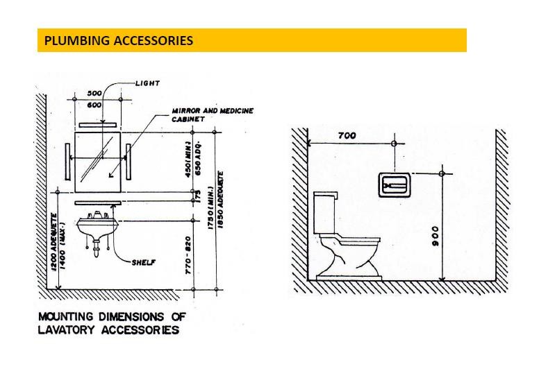
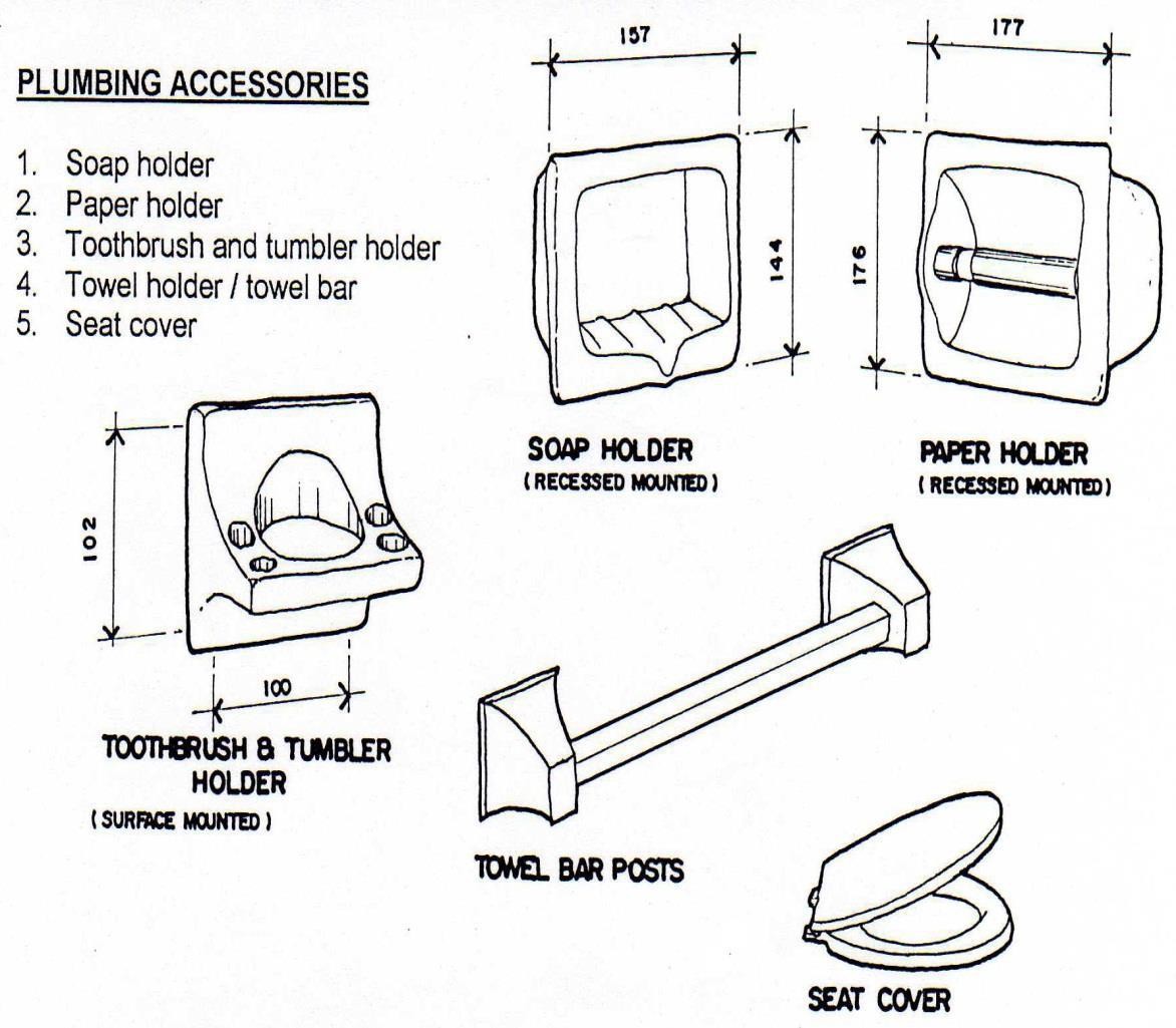 TOILET AND BATH PLUMBING ACCESSORIES
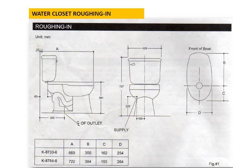
LESSON 3: PLUMBING FIXTURES: CLEARANCES, ROUGHING – IN DIMENSIONS AND FIXTURE UNIT VALUES (PART 2)
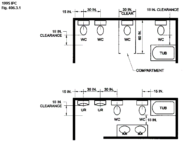
CLEARANCES – are minimum distances of fixtures for human safety and comfort.
ROUGHING – IN – is the installation of all piping and fitting parts of the plumbing system, which can be completed prior to the installation of fixtures and accessories. These include sanitary and storm drainage, tap, hot and chilled water supplies, gas piping, vent piping, and the necessary fixture supports.
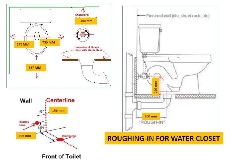 CLEARANCE DIMENSIONS FOR WATER CLOSET
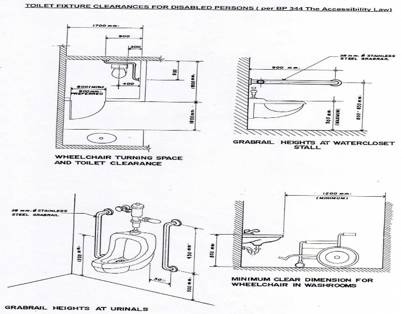
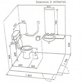 TOILET FOR THE DISABLED
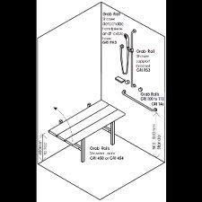
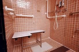
SHOWER FOR THE DISABLED
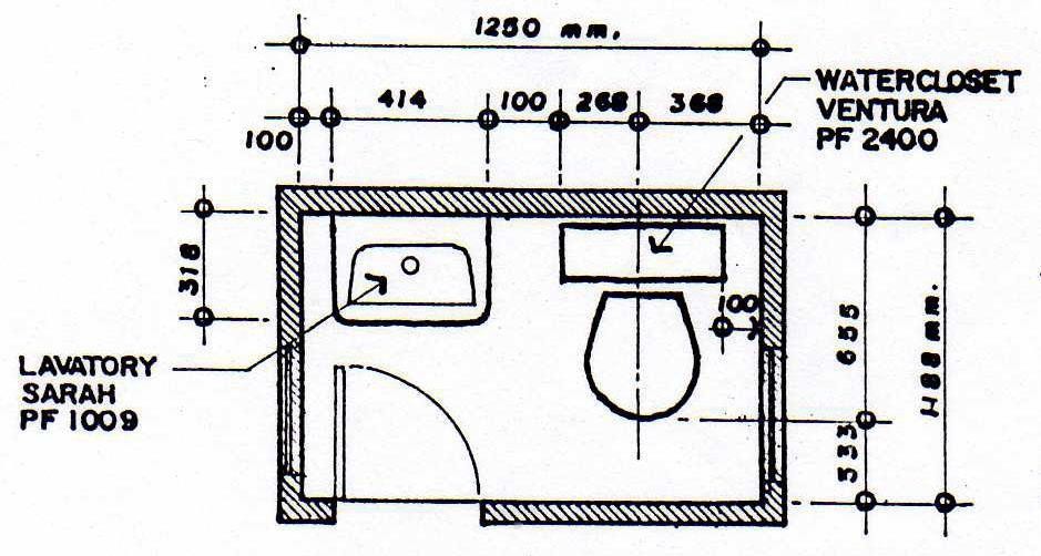
TOILET/POWDER ROOM PLAN
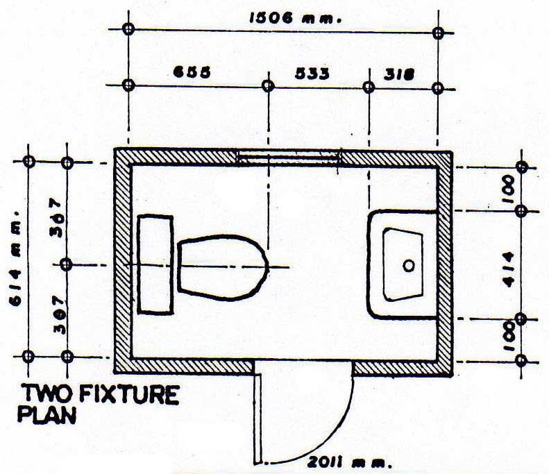
Two Fixture Plan: Parallel
Two Fixture Plan: Across
Three Fixture Plan: Open Type
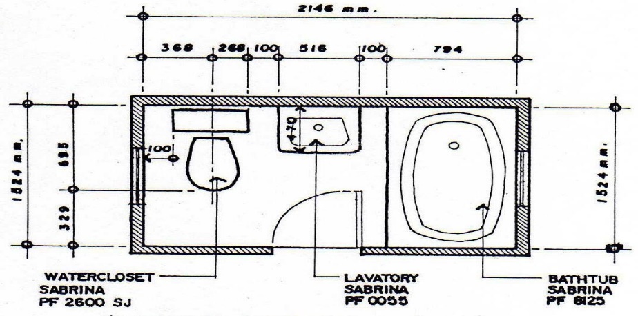
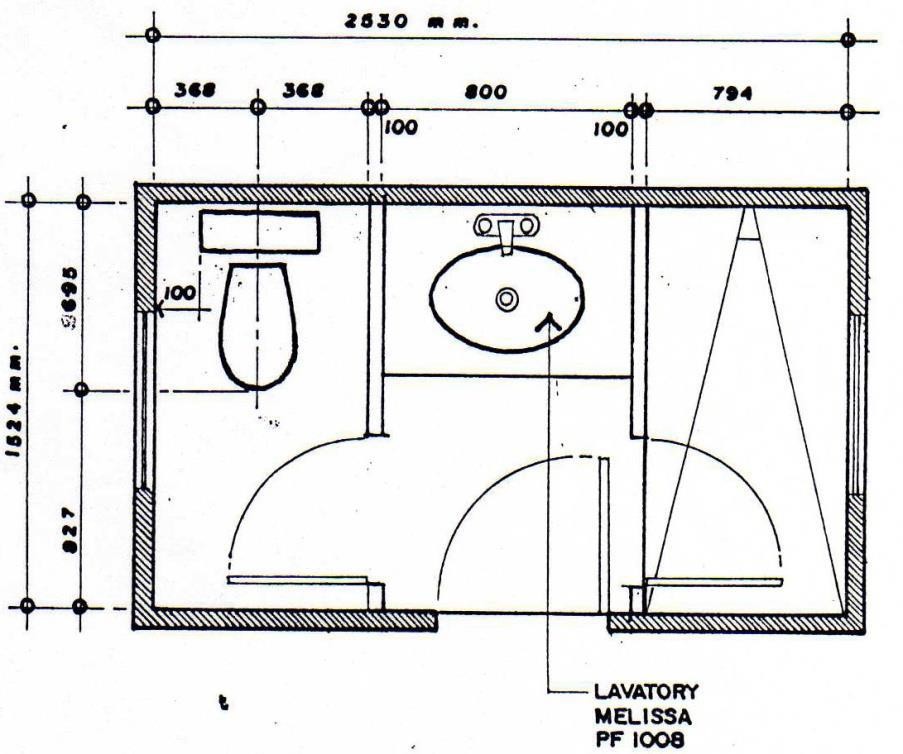
Three Fixture Plan: Compartment Type
FIXTURE UNIT, DRAINAGE FIXTURE UNIT AND WATER SUPPLY FIXTURE UNIT
Fixture Unit – is an arbitrary quantity in terms of which the load – producing effects or water requirements on the plumbing system of different kinds of plumbing fixtures are expressed in some arbitrarily chosen scale.
One fixture unit – is equivalent to a rate of flow at 28.3 liters per minute (1 cubic foot per minute) or (7.5 gpm).
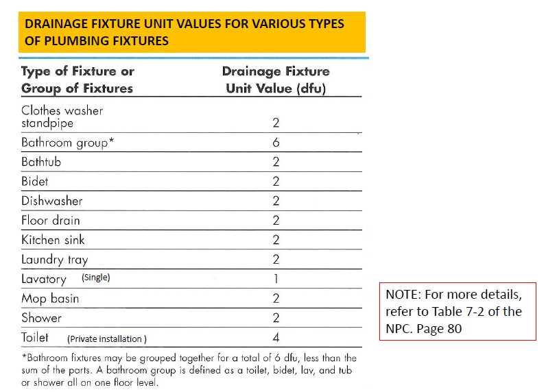
Drainage Fixture Unit (DFU) – is a numerical weighing factor to account for the probable discharge into the plumbing drainage system by various types of plumbing fixtures, using the single lavatory as equivalent to 1 DFU.
Water Supply Unit (WSFU) – is a numerical weighing factor to account for the water demand of various plumbing fixtures, using the lavatory for private use as equivalent to 1 WSFU.

LESSON 4: DWV SYSTEM
FOUR MAJOR COMPONENTS OF THE DRAINAGE SYSTEM
SANITARY OR SOIL DRAINAGE SYSTEM – the piping that conveys the discharge of water closets or fixture having similar functions (containing fecal matter), with or without the discharges from other fixtures.
WASTE DRAINAGE SYSTEM – the piping the receives the liquid discharge from plumbing fixtures other than water closets. It is free of fecal matter.
VENT SYSTEM – the piping installed to provide a flow of air to or from a drainage system or to provide a circulation of air within such system to protect trap seals from siphonage and back pressure.
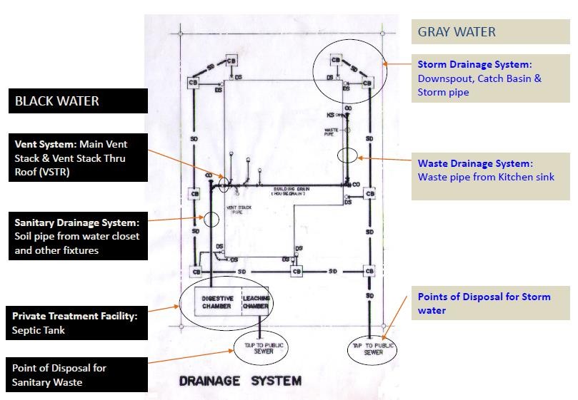 STORM DRAINAGE SYSTEM – the piping system that receives clear water drainage from leaders, downspouts, surface runoff, ground water, subsurface water, condensate water, cooling water or other similar discharges and conveys them to the point of disposal. All sanitary wastes must not be included in this system.
DEFINITION OF TERMS
Building Drain – is that part of the lowest horizontal piping of a drainage system which receives the discharge from soil, waste, and other drainage pipes inside the walls of the building and conveys it to the building sewer beginning 600 mm outside the building wall. It is also known as house drain.
Building Sewer – is that part of the horizontal piping of a drainage system which starts from the end of the building drain and receives the discharge of the building drain and conveys it to the public sewer, private sewer, individual sewage disposal system or other point of disposal.
House Sewer – is that part of a plumbing system extending from the house drain at a point 600mm from the outside face of the foundation wall of a building to the conjunction with the street sewer or to any point of discharge and conveying the drainage of one of the building sites.
Waste Pipe – a pipe which conveys only wastewater or liquid waste, free of fecal matter.
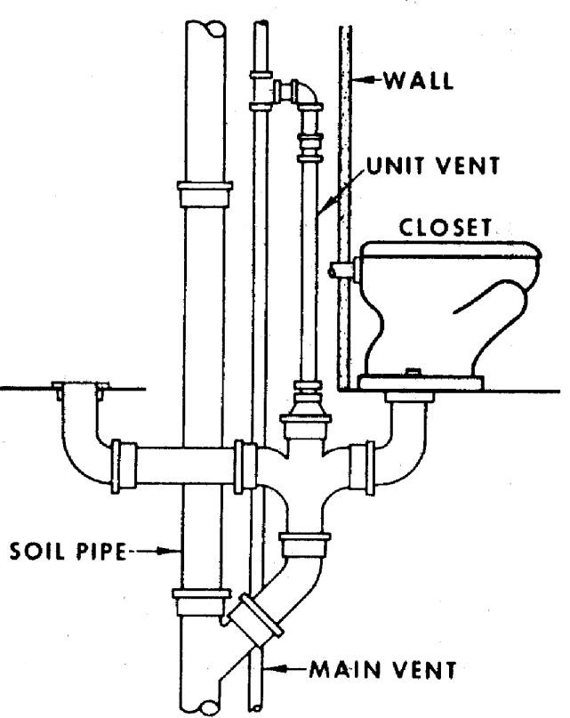
Soil Pipe – any pipe which conveys the discharge of water closet, urinal or fixtures having similar functions, with or without the discharges from other fixtures to the building drain or building sewer.
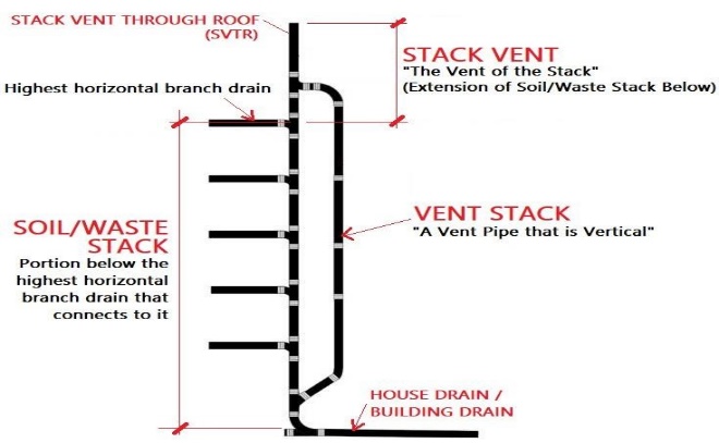
Soil Stack Pipe – a vertical soil pipe conveying fecal matter and wastewater.
Vent Pipe – a pipe or opening used for ensuring the circulation of air in a plumbing system and for relieving the negative pressure exerted on trap seals.
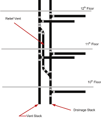
Vent Stack – the vertical vent pipe installed primarily for providing circulation of air to and from any part of the soil, waste of the drainage system.
Stack Vent – the extension of a soil or waste stack above the highest horizontal.
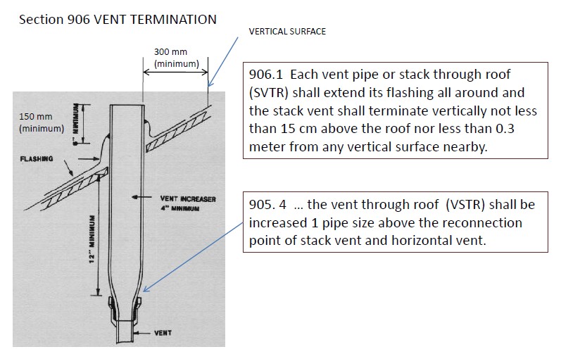
Stack Vent Through Roof (SVTR) – the uppermost end of the stack vent above the roof.
Branch Vent – a horizontal vent connecting one or more individual vertical back vents with the vent stack or stack vent.
DRAINAGE TRAPS
Drain – is a pipe, which carries ground and surface waters, storm water or wastewater into a building drainage system.
Common Types of Drains
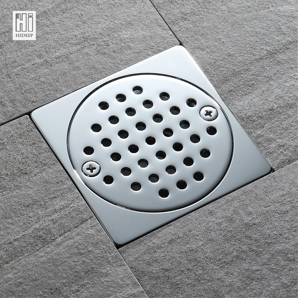
Floor Drains
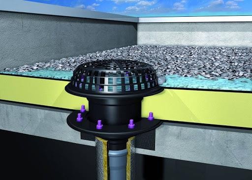
Roof Drains
Types of Drain Connections
Direct Drain Connection
Indirect Drain Connection
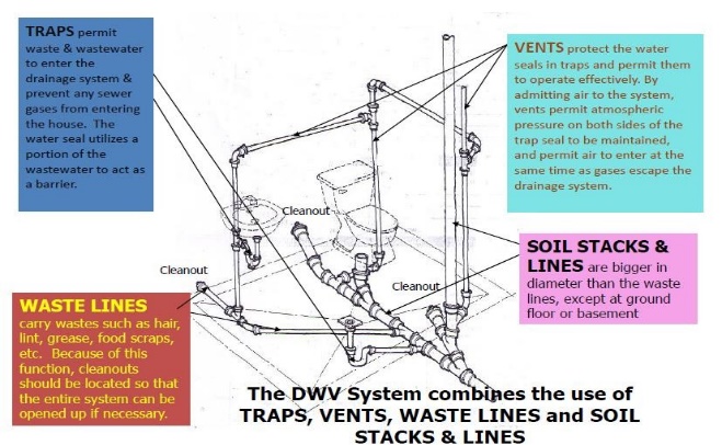
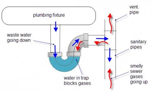
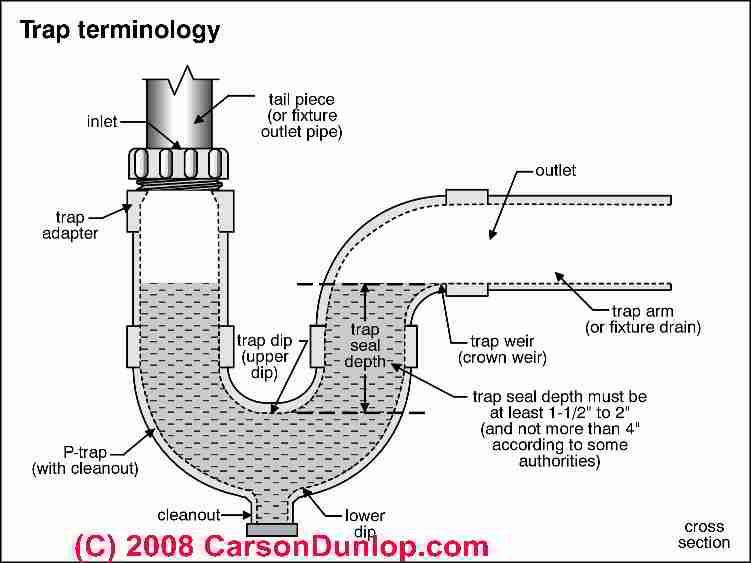
TRAP – is a fitting or device designed and constructed to provide, when properly vented, a liquid seal which prevents the backflow of foul air or methane gas without materially affecting the flow of sewage or wastewater through it.
Types of Water Sealed Traps
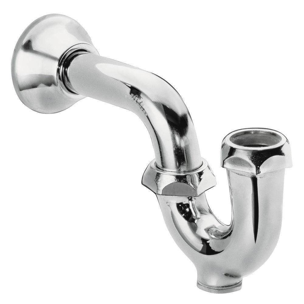
P – Trap – is the most widely used for fixtures, common diameter sizes are 32 mm (1 – ¼”) and 38 mm (1 – ½”).
Drum Trap – is used mostly for bathtubs. It has the advantage of containing a larger volume of water and discharging a greater volume of water than a P – trap.
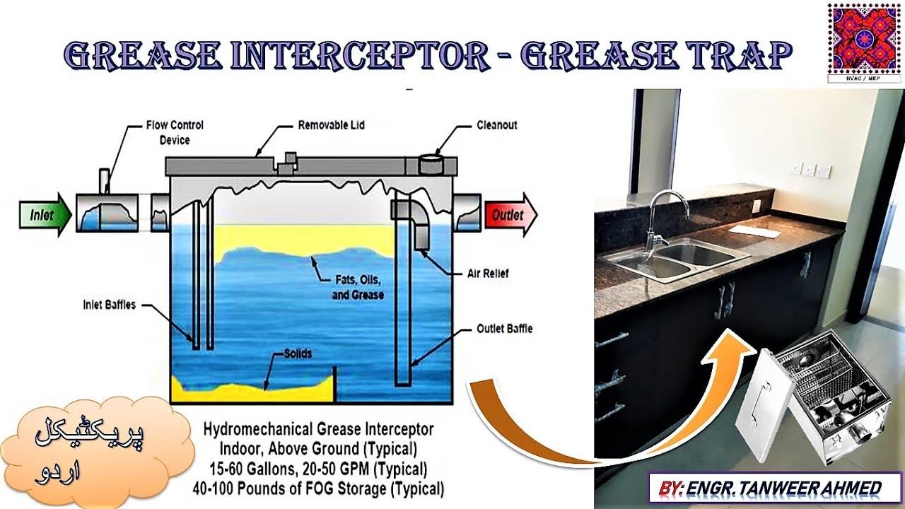
Grease Interceptor/ Grease Trap – grease interceptor is an interceptor of at least 3 cubic
meter capacity to serve one or more fixtures and which is remotely located. Grease trap is a device designed to retain grease from one to a maximum of four fixtures.
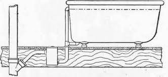
House Trap/ Running Trap – a device installed to prevent circulation of air between the drainage of the building and the building sewer.
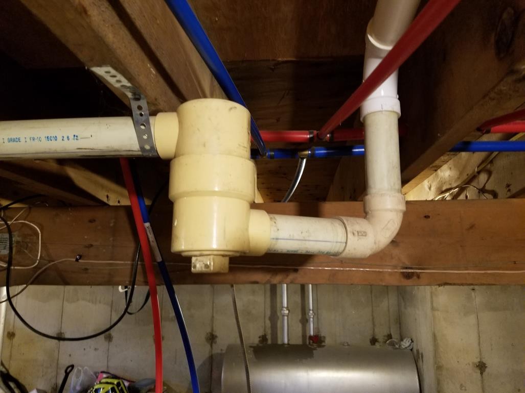
 P – TRAPS
 DRUM TRAPS
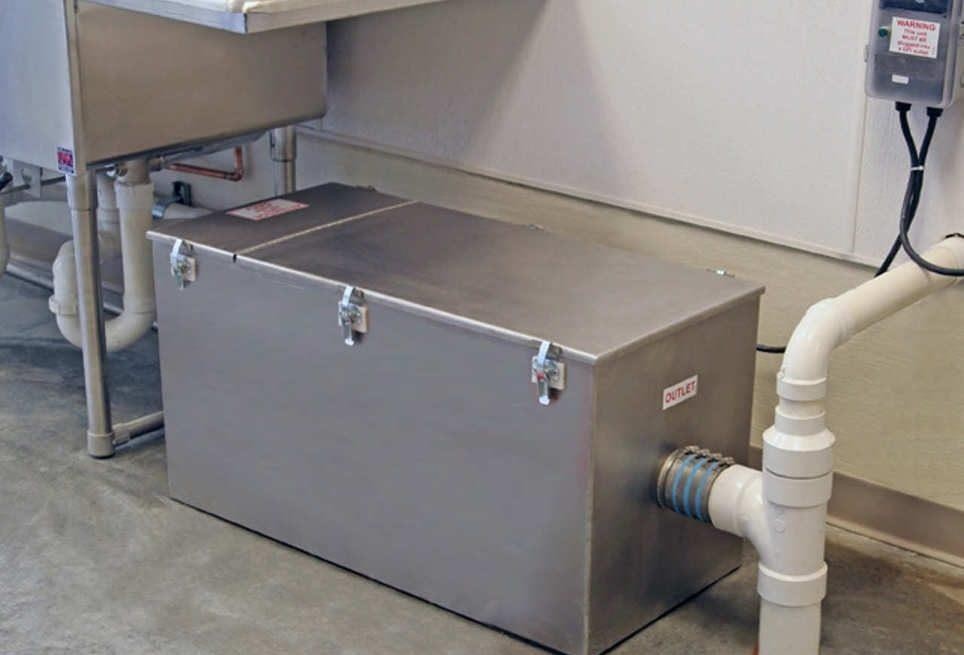
GREASE TRAPS
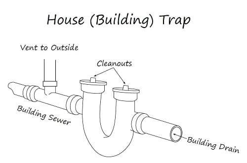
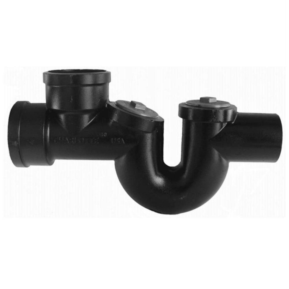 HOUSE TRAPS
DRAINAGE VENT
VENT – is a pipe or opening that brings outside air into the plumbing system and equalizes the pressure on both sides of a trap to prevent trap seal loss.
- Inadequate ventilation usually causes the loss of trap seal.
- At sea level, atmospheric pressure is about 102 kPa (14.75 psi). Any difference between this pressure and the pressure on the discharge side forces the water seal into the direction of less pressure. Venting the discharge side of the trap to the atmosphere tends to equalize these pressures.
CAUSE OF TRAP SEAL LOSS
Siphonage – the withdrawal of a liquid from a trap due to a suction caused by liquid flow in a pipe without proper ventilation.
Direct or Self – siphonage
Indirect or Momentum Siphonage
Back Pressure or Back Siphonage – pressure developed in opposition to the flow of liquid in a pipe in a pipe due to friction, gravity, or some other restriction to the flow of the conveyed liquid.
Evaporation – occurs when a fixture is not used for a long time.
Capillary Attraction – a foreign object lodged in the trap causes loss of trap seal by capillary action by acting as a wick.
Wind Effect
TYPES OF VENTS
Soil and waste vent
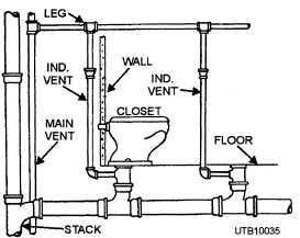
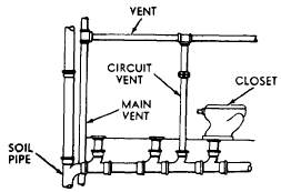
Main vent
Individual/ Vent or Back Vent
Unit Vent
Circuit Vent or Loop Vent
Relief Vent
Yoke Vent
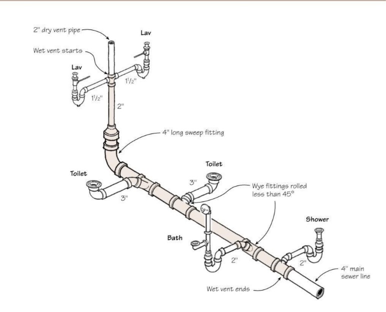
Wet Vent
Looped Vent
Local Vent
Utility Vent
LESSON 5: WATER SUPPLY AND DISTRIBUTION SYSTEM (PART 1)
ELEMENTS OF DOMESTIC WATER DISTRIBUTION SYSTEM
Water (Street) Main
A water supply pipe for public or community use controlled by public authority.
Water –Service Pipe
The pipe from the water main, water meter, water supply system or other approved source of water supply, to the building or structure served.
Water –Distribution Pipe
A pipe which conveys potable water from the building supply pipe to the plumbing fixtures & other water outlets in the building.
Fixture Branch
A pipe connecting several fixtures.
Fixture Supply
A water supply pipe connecting the fixture with the fixture branch or directly to a main water supply pipe.
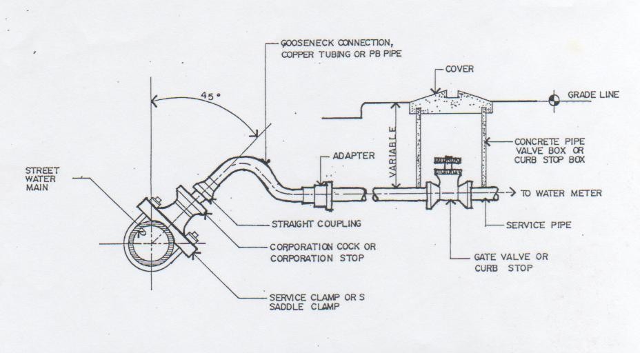
SERVICE TAP CONNECTION DETAILS
Corporation Cock
A valve screwed into the street water main to supply the house service connection.
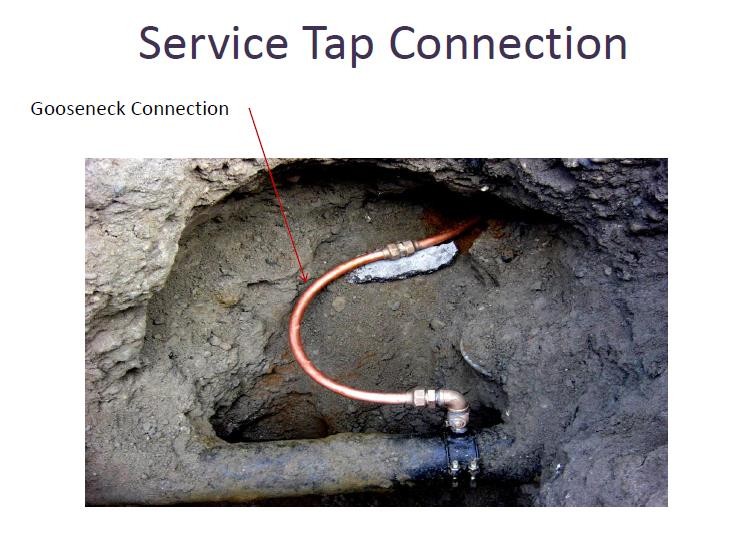
Gooseneck
The part of the pipe curved like the neck of a goose, usually flexible. Also, the lead connection between a service pipe and water main.
Curb Stop or Curb Cock
A control valve for the water supply of a building, usually placed between the sidewalk and the street curb; used to shut off the water supply in case of emergency or should the water supply of the building be discontinued.
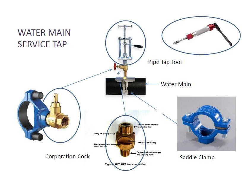
SERVICE TAP CONNECTION
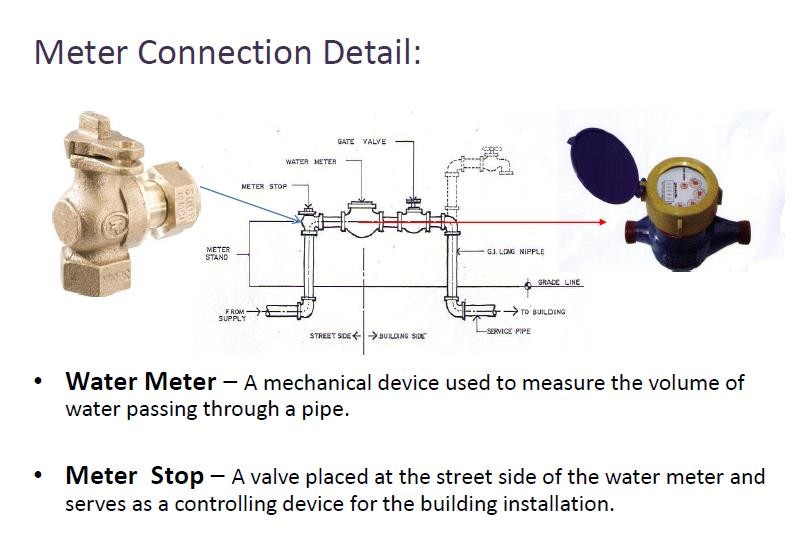
METER CONNECTION DETAIL
Water Meter – a mechanical device used to measure the volume of water passing through a pipe.
Meter Stop – a valve placed at the street side of the water meter and serves as a controlling device for the building installation.
HOUSE DISTRIBUTION LAY – OUT: FIXTURE SUPPLY

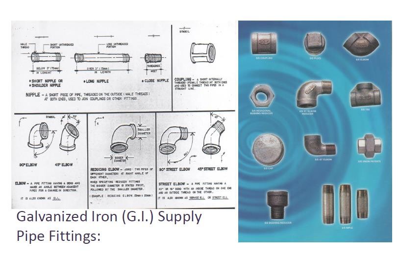
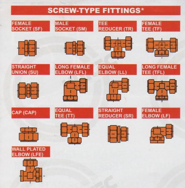
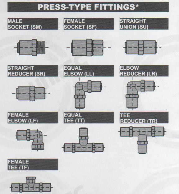
PIPES AND FITTINGS FOR WATER SUPPLY AND DISTRIBUTION SYSTEM
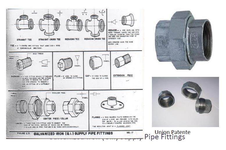
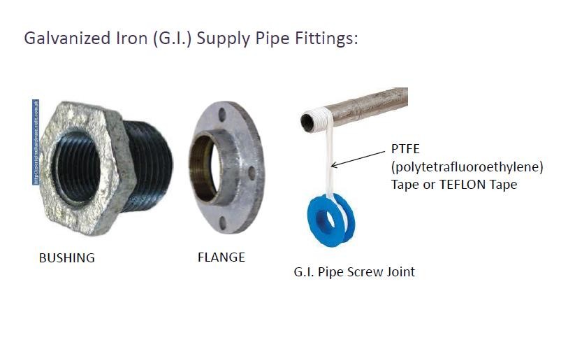
G.I. PIPES AND FITTINGS
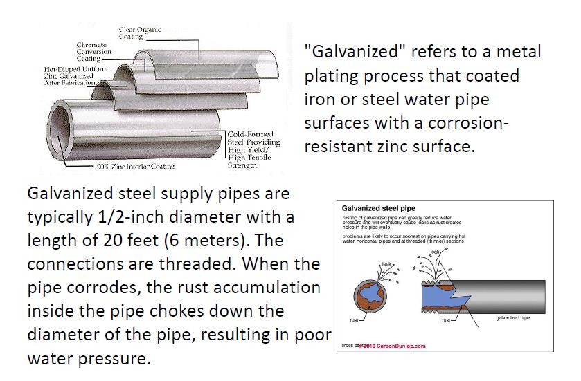
Galvanized refers to a metal plating process that coated iron or steel water pipe surfaces with a corrosion resistant zinc surface.
Galvanized steel supply pipes are typically ½ - inch diameter with a length of 20 feet (6 meters). The connections are threaded. When the pipe corrodes, the rust accumulation inside the pipe chokes down the diameter of the pipe, resulting in poor water pressure.
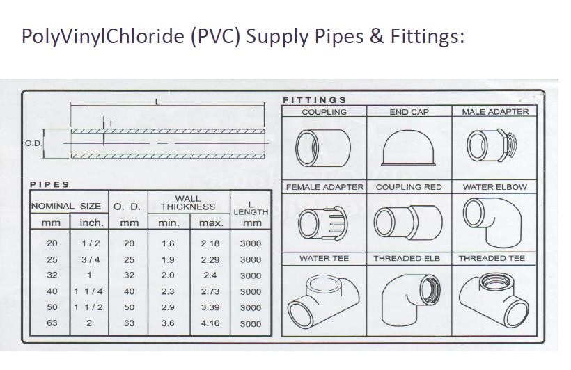
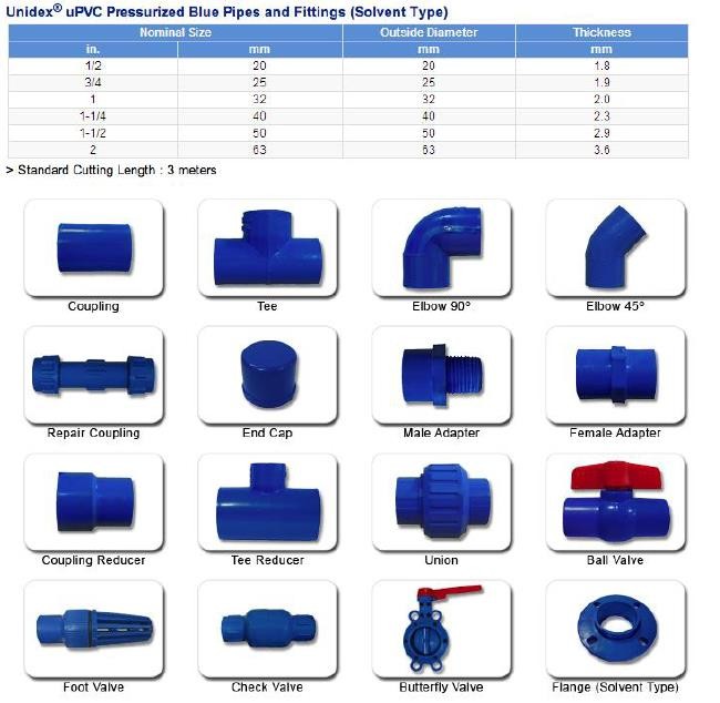
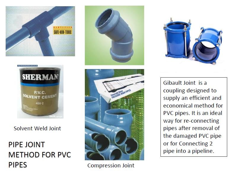
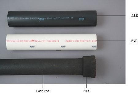
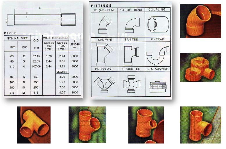
PVC PIPES AND FITTINGS
POLYVINYL CHLORIDE, commonly abbreviated PVC, is the third-most widely produced plastic after polyethylene and polypropylene. PVC is used in construction because it is more effective than traditional materials such as copper, iron or wood in pipe and profile applications.
In the water distribution market, it accounts for 66% of the market in the US, and in sanitary sewer pipe applications, it accounts for 75%. Its light weight, low cost, and low maintenance make it attractive. However, it must be carefully installed and bedded to ensure longitudinal cracking does not occur. Additionally, PVC pipes can be fused together using various solvent cements, creating permanent joints.
uPVC = Unplasticized Polyvinyl Chloride
CPVC= Chlorinated Polyvinyl Chloride
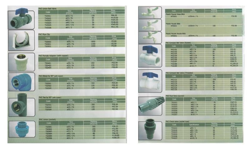
POLYVINYL CHLORIDE (PVC) SUPPLY PIPES AND FITTINGS

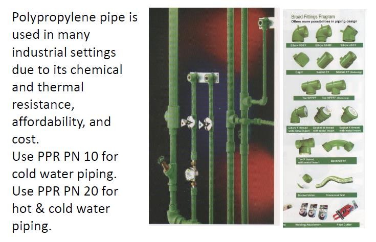
POLYPROPYLENE (PPR) PIPES AND FITTINGS
Polypropylene pipe is used in many industrial settings due to its chemical and thermal resistance affordability, and cost.
Use PPR PN 10 for cold water piping.
Use PPR PN 20 for hot and cold-water piping.
POLYETHYLENE (PE) PIPES AND FITTINGS
High-Density Polyethylene Pipe (HDPE or PE Pipe) is made from ethylene, which can be derived from either crude oil or natural gas.
PE pipe is extremely strong, durable, flexible, corrosion free and chemical resistant. These features make it perfect for a variety of underground conditions and help it last up to 100 years.
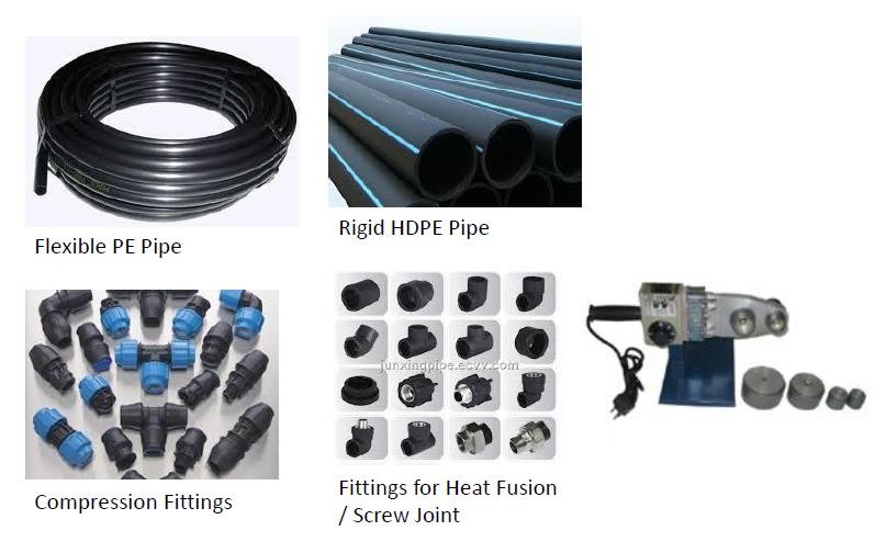 The smooth walls allow for less friction, which increase flow through the same diameter as that of other pipes.
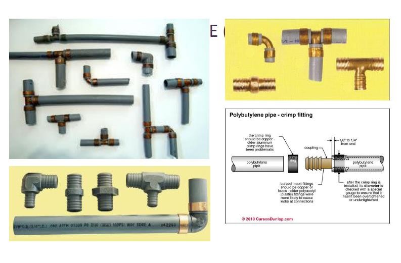
POLYBUTYLENE (PB) PIPES AND FITTINGS
Polybutylene is a form of plastic resin that was used extensively in the manufacture of water supply piping from 1978 until 1995. Due to the low cost of the material and ease of installation, polybutylene piping systems were viewed as "the pipe of the future" and were used as a substitute for traditional copper piping
The piping systems were used for underground water mains and as interior water distribution piping.

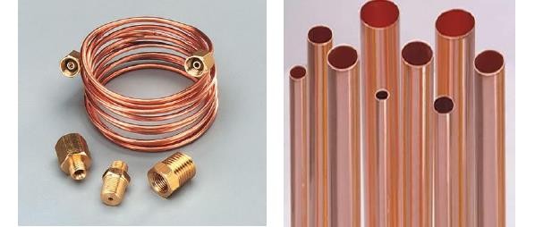
COPPER PIPES AND FITTINGS
Copper tubing is most often used for supply of hot and cold tap water, and as refrigerant line in HVAC systems. There are two basic types of copper tubing, soft copper, and rigid copper. Copper tubing is joined using flare connection, compression connection, or solder. Copper offers a high level of resistance to corrosion but is becoming very costly.
WALL THICKNESS OF COPPER TUBING
Type K has the thickest wall section of the three types of pressure rated tubing and is commonly used for deep underground burial such as under sidewalks and streets, with a suitable corrosion protection coating or continuous polyethylene sleeve as required by code. It is color coded in green.
Type L has a thinner pipe wall section and is most popular for use in water supply system. It is color coded in blue.
Type M has an even thinner pipe wall section and is used in residential and commercial water supply where pressure is not too great. It is color coded in red.
Type DWV has the thinnest wall section, and is generally only suitable for unpressurized applications, such as drains, waste, and vent (DWV).
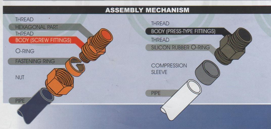
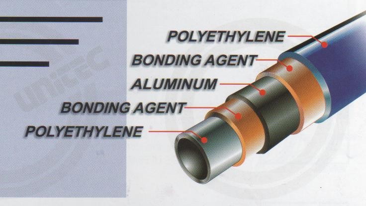 COMPOSITE PIPE
LESSON 5: WATER SUPPLY AND DISTRIBUTION SYSTEM (PART 2)
PIPE SIZE CALCULATION IN DIRECT PRESSURE SYSTEM
STEP 1. Secure the following data.
Pressure at water main
Total fixture load in the system measured in Water Supply Fixture Units (WSFU). Use Table 1.0
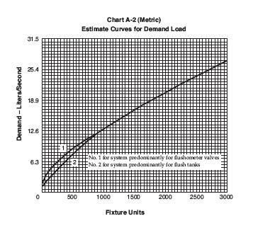
Estimate water demand based on the predominant flushing mechanism used. Use Chart A – 2 and A – 3 or Table 2.1 or Table 2.2
Type of fixture being considered as the topmost fixture.
Height of the topmost fixture measured from the street level.
Length of piping measured from the water main up to the farthest and topmost fixture.
Fixture pressure requirement of the topmost fixtures.
Notes:
A 1.1. Obtain the necessary information regarding the minimum daily service pressure in the area where the building is to be located.
A 1.3. Obtain all available local information regarding the use of different kinds of pipe with respect both to durability and to decrease in capacity with length of service in the particular water supply.
Section 607.1. The minimum pressure at water main shall be 103 kPa (15 psi).
Section 607.2. The maximum pressure at the water main shall be 551 kPa (80 psi).
Water Supply Fixture Unit (WSFU) – is a numerical weighing factor to account for the water demand of various plumbing fixtures, using the lavatory (for private use) as 1 WSFU. It is just an index number meant to put all fixtures on a common basis.
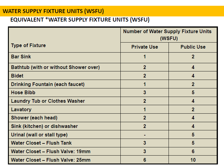
Table 1.0 EQUIVALENT WATER SUPPLY FIXTURE UNITS (WSFU)
Type of Fixture | Number of Water Supply Fixture Units (WSFU) | |
Private Use | Public Use | |
Bar Sink | 1 | 2 |
Bathtub (with or without shower over | 2 | 4 |
Bidet | 2 | 4 |
Drinking Fountain (each faucet) | 1 | 2 |
Hose Bibb | 3 | 5 |
Laundry Tub or Clothes Washer | 2 | 4 |
Lavatory | 1 | 2 |
Shower (each head) | 2 | 4 |
Sink (kitchen) or dishwasher | 2 | 4 |
Urinal (wall or stall type) | - | 5 |
Water Closet – Flush Tank | 3 | 5 |
Water Closet – Flush Valve: 19 mm | 3 | 6 |
Water Closet – Flush Valve: 25 mm | 6 | 10 |
* This table is taken from Table 6 – 5 in the National Plumbing Code of the Philippines, page 73. Also, Table A – 1 in “Annex A” of the Code, page 167 is similar (with the addition of Minimum Connections for Cold – water and Hot – water).
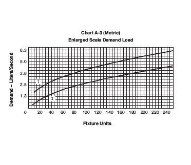
*A 2.1 Estimate the supply demand for the building main and the principal branches and risers of the system by totaling the fixture units and then reading the corresponding ordinate from Chart A – 2 or A – 3, whichever is applicable.
* This is found on page 172 of the National Plumbing Code of the Philippines.
* This is found on page 173 of the National Plumbing Code of the Philippines.
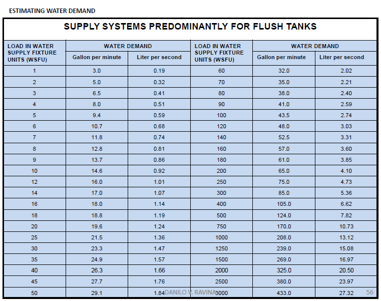
Table 2.1 ESTIMATING WATER DEMAND
SUPPLY BY SYSTEMS PREDOMINANTLY FOR FLUSH TANKS | |||||
Load in WSFU | Water Demand | Load in WSFU | Water Demand | ||
Gal/min | Lit/sec | Gal/min | Lit/sec | ||
1 | 3.0 | 0.19 | 60 | 32.0 | 2.02 |
2 | 5.0 | 0.32 | 70 | 35.0 | 2.21 |
3 | 6.5 | 0.41 | 80 | 38.0 | 2.40 |
4 | 8.0 | 0.51 | 90 | 41.0 | 2.59 |
5 | 9.4 | 0.59 | 100 | 43.5 | 2.74 |
6 | 10.7 | 0.68 | 120 | 48.0 | 3.03 |
7 | 11.8 | 0.74 | 140 | 52.5 | 3.31 |
8 | 12.8 | 0.81 | 160 | 57.0 | 3.60 |
9 | 13.7 | 0.86 | 180 | 61.0 | 3.85 |
10 | 14.6 | 0.92 | 200 | 65.0 | 4.10 |
12 | 16.0 | 1.01 | 250 | 75.0 | 4.73 |
14 | 17.0 | 1.07 | 300 | 85.0 | 5.36 |
16 | 18.0 | 1.14 | 400 | 105.0 | 6.62 |
18 | 18.8 | 1.19 | 500 | 124.0 | 7.82 |
20 | 19.6 | 1.24 | 750 | 170 | 10.73 |
25 | 21.5 | 1.36 | 1000 | 208.0 | 13.12 |
30 | 23.3 | 1.47 | 1250 | 239.0 | 15.08 |
35 | 24.9 | 1.57 | 1500 | 269.0 | 16.97 |
40 | 26.3 | 1.66 | 2000 | 325.0 | 20.50 |
45 | 27.7 | 1.76 | 2500 | 380.0 | 23.97 |
50 | 29.1 | 1.84 | 3000 | 433.0 | 27.32 |
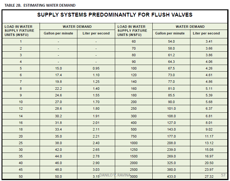
Table 2.2 ESTIMATING WATER DEMAND
SUPPLY BY SYSTEMS PREDOMINANTLY FOR FLUSH VALVES | |||||
Load in WSFU | Water Demand | Load in WSFU | Water Demand | ||
Gal/min | Lit/sec | Gal/min | Lit/sec | ||
1 | - | - | 60 | 54.0 | 3.41 |
2 | - | - | 70 | 58.0 | 3.66 |
3 | - | - | 80 | 61.2 | 3.86 |
4 | - | - | 90 | 64.3 | 4.06 |
5 | 15.0 | 0.95 | 100 | 67.5 | 4.26 |
6 | 17.4 | 1.10 | 120 | 73.0 | 4.61 |
7 | 19.8 | 1.25 | 140 | 77.0 | 4.86 |
8 | 22.2 | 1.40 | 160 | 81.0 | 5.11 |
9 | 24.6 | 1.55 | 180 | 85.5 | 5.39 |
10 | 27.0 | 1.70 | 200 | 90.0 | 5.68 |
12 | 28.6 | 1.80 | 250 | 101.0 | 6.37 |
14 | 30.2 | 1.91 | 300 | 108.0 | 6.81 |
16 | 31.8 | 2.01 | 400 | 127.0 | 8.01 |
18 | 33.4 | 2.11 | 500 | 143.0 | 9.02 |
20 | 35.0 | 2.21 | 750 | 177.0 | 11.17 |
25 | 38.0 | 2.40 | 1000 | 208.0 | 13.12 |
30 | 42.0 | 2.65 | 1250 | 239.0 | 15.08 |
35 | 44.0 | 2.78 | 1500 | 269.0 | 16.97 |
40 | 46.0 | 2.90 | 2000 | 325.0 | 20.50 |
45 | 48.0 | 3.03 | 2500 | 380.0 | 23.97 |
50 | 50.0 | 3.15 | 3000 | 433.0 | 27.32 |
STEP 2. Find the pressure required in the system to provide the minimum fixture pressure (A) for the uppermost fixture.
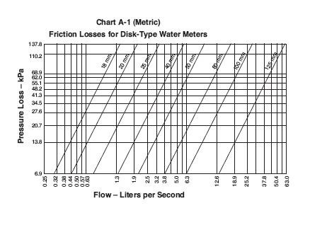 Table 3.0 PROPER FLOW AND PRESSURE REQUIRED DURING FLOW FOR DIFFERENT
Fixture Fitting | Flow Pressure | Flow | ||
kPa | Psi | Gal/min | Lit/sec | |
Ordinary Lavatory Faucet | 55 | 8 | 2.0 | 0.13 |
Self – closing Lavatory Faucet | 83 | 12 | 2.5 | 0.16 |
Sink Faucet (9mm) | 69 | 10 | 3.5 | 0.22 |
Sink Faucet (12mm) | 35 | 5 | 4.5 | 0.28 |
Drinking Fountain Jet | 55 | 8 | 0.75 | 0.05 |
Washing Machine/Dishwasher | 55 | 8 | 4.0 | 0.25 |
Laundry Faucet | 35 | 5 | 5.0 | 0.32 |
Bathtub Faucet | 35 | 5 | 5.0 | 0.32 |
Shower Head (12mm) | 83 | 12 | 5.0 | 0.32 |
Ball Cock for Water Closet (Flush Tank) | 104 | 15 | 3.0 | 0.19 |
Flush Valve for Water Closet (19mm) | 104 | 15 | 27.0 | 1.70 |
Flush Valve for Water Closet (25mm) | 172 | 25 | 35.0 | 2.21 |
Flush Valve for Urinal (19mm) | 104 | 15 | 15.0 | 0.95 |
Garden Hose, 15m and Sill Cock | 207 | 30 | 5.0 | 0.32 |
* A 3.1 Decide what is the desirable minimum pressure that should be maintained at the highest fixture in the supply system. If the highest group of the fixtures contains flushometer valves, the pressure for the group should not be less than 103.42 kPa (15 psi). For flush tank supplies, the available pressure may not be less than 55.16 kPa (8 psi).
STEP 3. Calculate the Static Head (B)
* A 3.2 Determine the elevation in meters of the highest fixture or group of fixtures above the water (street) main. Multiply this difference in elevation by 9.79. The result is in the loss in static pressure in kPa.
STEP 4. Using the Demand Load, determine the Pressure Loss in the water meter (C).
* A 1.2 If the supply is to be metered, obtain information regarding friction loss relative to the rate of flow for meters in the range of sizes likely to be used. Friction – loss data can be obtained from most manufacturers of water meters. Friction losses for disk type meters may be obtained from Chart A – 1.
STEP 5. Calculate the Pressure Available (Pa) for friction loss in the supply pipes.
where:
A – minimum fixture pressure requirement
B – static head
C – pressure loss at water meter
* A 3.3 Subtract the sum of loss in static pressure and the pressure to be maintained at the highest fixture from the average minimum daily service pressure. The result will be the pressure available for fiction loss in the supply pipes if no water meter is used. If a meter is to be installed, the friction loss in the meter for the estimated maximum demand should also be subtracted from the service pressure to determine pressure loss available for friction loss in the supply pipes.
STEP 6. Determine the developed length (DL) of the supply pipe, including the equivalent length of fittings (DL’)
* A 3.4 Determine the developed length of pipe from the water (street) main to the highest fixture. If close estimates are desired, compute with the aid of Table A – 2; the equivalent length of pipe for all fittings in the line from the water (street) main to the highest fixture and add the sum to the developed length.
STEP 7. Calculate Total Equivalent Length (TEL) of the piping.
where:
DL – length of the piping (horizontal and vertical) measured from the water main up to the farthest and topmost fixture.
DL’ – equivalent length of fittings, if piping diagram is not available, use 20% to 50% of DL.
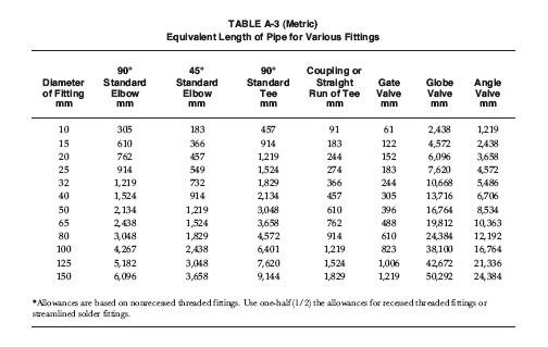
* This table is like Table A – 2 on page 168 of the National Plumbing Code of the Philippines.
STEP 8. Calculate the Average Permissible Friction Loss per meter length pf pipe (Pf).
* A 3.4 The pressure available for friction loss in kPa divided by the developed length of pipe from the water (street) main to the highest fixture times one hundred (100), will be the average permissible friction loss per 30.4m length of pipe.
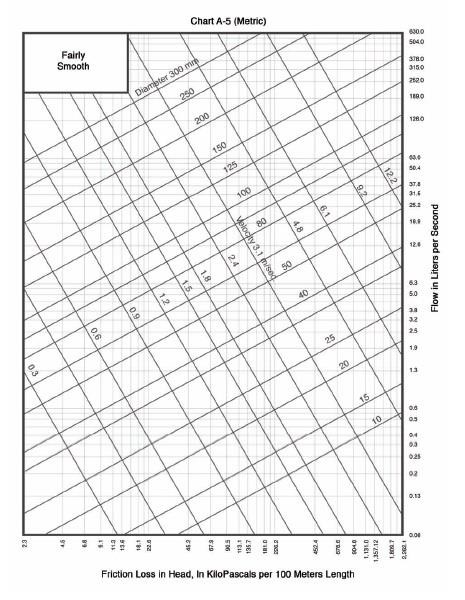
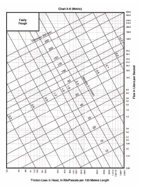
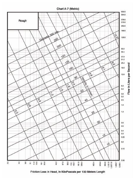
STEP 9. Using the Demand Load and the Average Permissible Friction Loss (Pa) determine an approximate pipe size that is closest to the velocity of 3m/s. Use Charts A – 5, A – 6 and A – 7.
* A 4.1 Knowing the permissible friction loss per 30.4m of pipe and the total demand, the diameter of the diameter of the building supply pipe may be obtained from charts A – 4, A – 5, A – 6, or A – 7, whichever is applicable. The diameter of the pipe on or next above the coordinate point corresponding to the estimated total demand and the permissible friction loss will be the size needed up to the first branch from the building supply pipe.
EXAMPLE
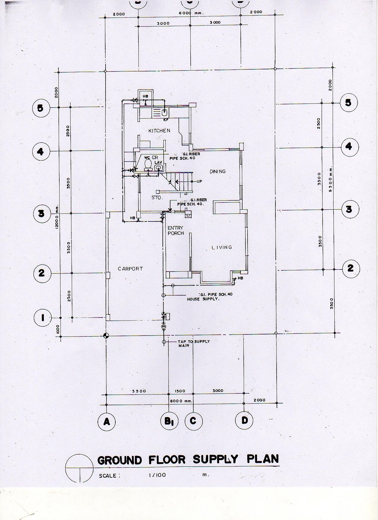
Step 1.
Ground Floor Fixture Load:
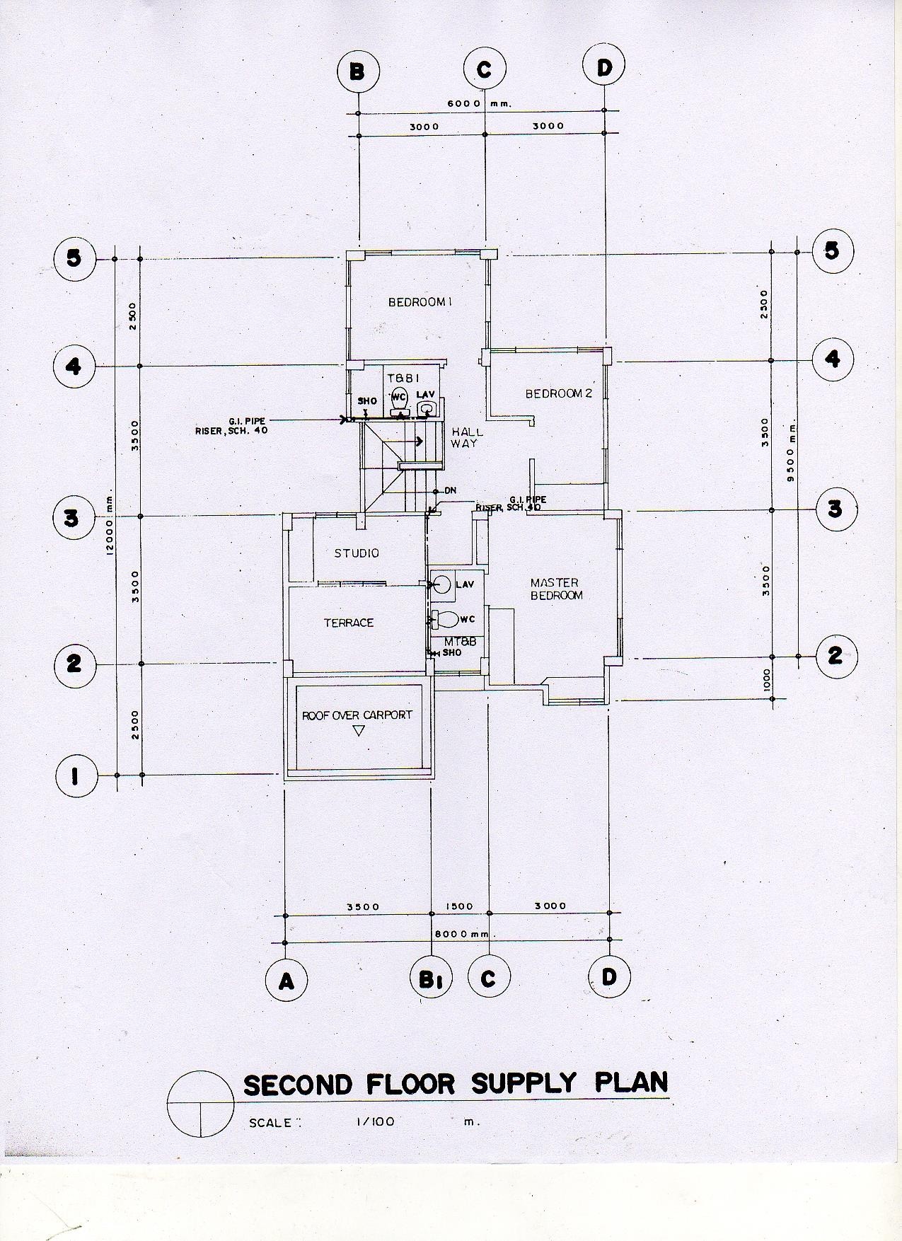
Second Floor Fixture Load:
USEFUL DATA
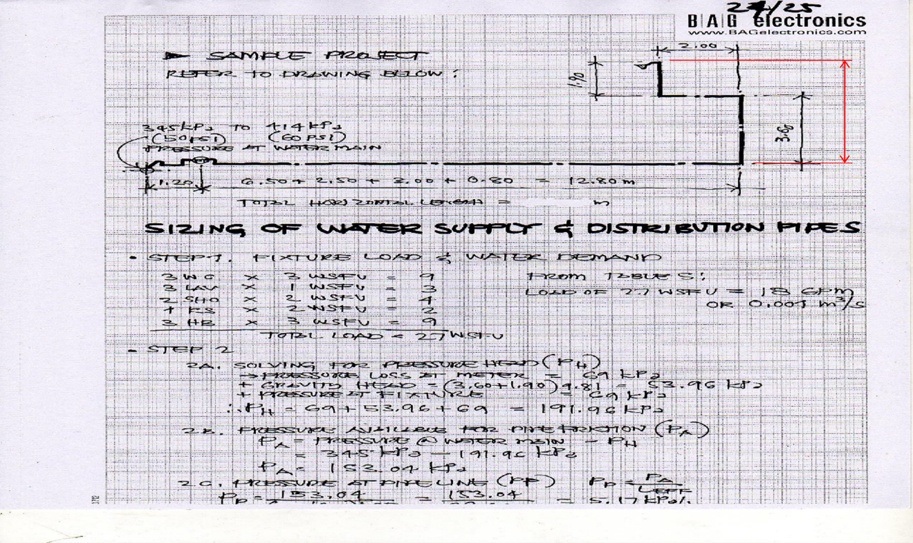
a. Average pressure at water main | 345 kPa (50 psi) |
b. Total fixture load | 27 wsfu |
c. Estimated water demand | 1.30 lps |
d. Type of topmost fixture | Shower |
e. Height of topmost fixture | 5.50 m |
f. Length of piping | 21.50 m |
g. Fixture pressure requirement at topmost fixture | 104 kPa |
Step 2.
Step 3.
Step 4.
Step 5.
Step 6.
Step 7.
Step 8.
Step 9.
LESSON 6. DOMESTIC WATER HEATING
WHY DO WE NEED HOT WATER SUPPLY?
Personal Hygiene – to maintain the body clean, a regular supply of hot water is required to break down and dissolve oil & dirt. Soap lathers much better in hot water than cold. Hot water is more friendly to our skin temperature since we are warm-blooded animals. Hot water also helps to open skin pores, letting the soap get down into the tissue to lift out the oil & dirt.
Washing – certain substances, such as fatty foods on a plate, require a temperature of 60 degrees Centigrade to lift them.
TYPES OF FUEL
Electricity
Solid Fuel
Gas
Solar
Steam
Oil
Heat Pumps
TYPES OF SYSTEM
Localized Water Heating
Centralized Hot Water Systems
Storage Water Heaters
Instantaneous Water Heaters
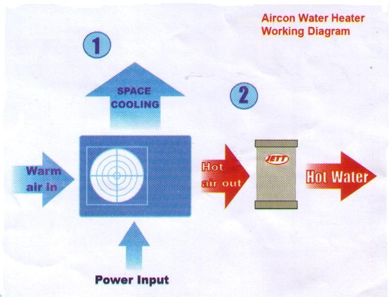
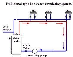
OPERATING PRINCIPLE OF HOT WATER SUPPLY
The storage tank & heating device of a hot water supply & distribution system are so assembled as to create a circulation of water within them.
The movement of the water is the result of molecular activity. The application of heat to a body of water causes it to expand & become less dense, which give it a natural tendency to rise.
The inequality of weights between the hot & the cold water contained in the tank results in the circulation of the liquid.
BASIC CONSIDERATIONS
Type of Heating System
Direct System
Range Boilers
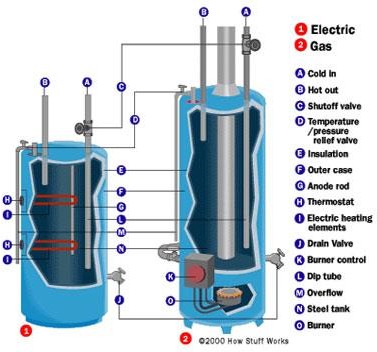
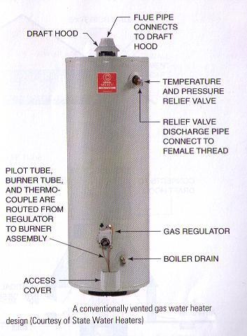
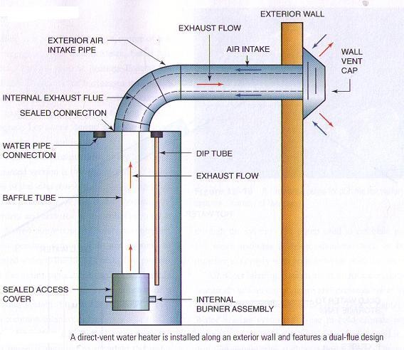
Gas Water Heater
Oil-Fired Water Heater
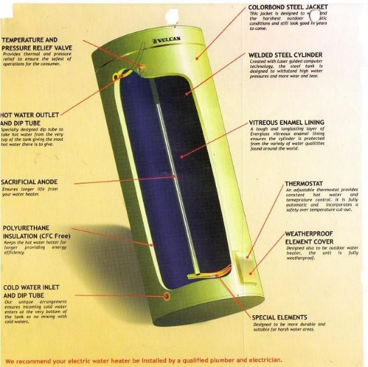
Electric Water Heater
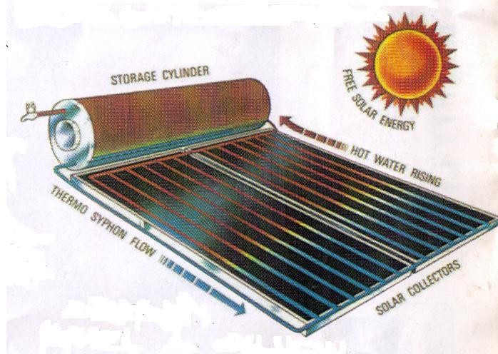
Solar Water Heater
Indirect System
Prismatic Cylinder
Calorifiers
Annular Cylinder
Type of Tank Connection
Vertical position
Horizontal position
Pipes, Valves & Fittings
Type of Installation
Up feed & Gravity Return
Overhead Feed & Gravity Return
Pump Circuit System
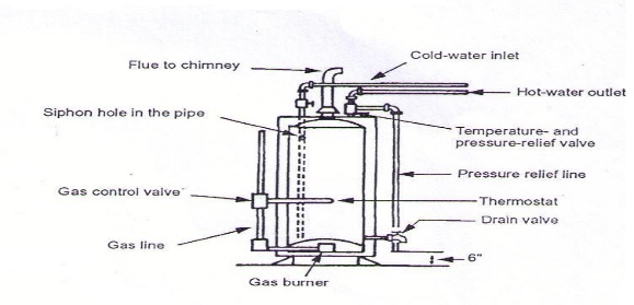
RANGE BOILER
In this system, the water that is being heated by the boiler is used out of the hot water faucets.
Range Boiler - is a small cylindrical hot water tank that varies in size from 300 mm to 600 mm in diameter & is not more than 1800 mm long. It is made of galvanized steel of Standard & Extra Heavy Gauge.
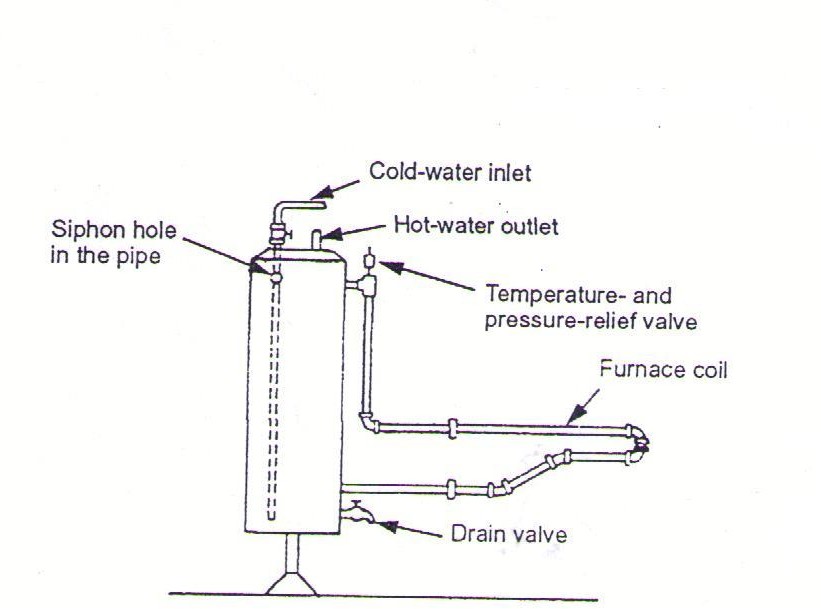
RANGE BOILER AND FURNACE OIL
The range boiler is usually mounted upright on a stand. A drain is placed at the bottom to remove sediment; a temperature & pressure relief valve is placed at the top for safety. The furnace coil is in the furnace box.
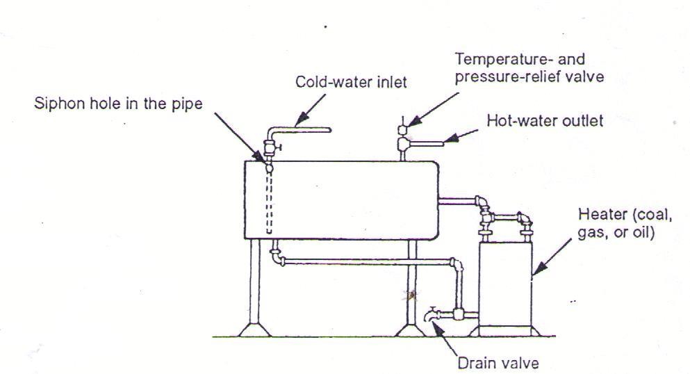
RANGE BOILER AND HEATER
The range boiler is usually installed horizontally on a stand. The heater may be fired by coal, gas, or oil.
The Equipment
 The Installation
The Operating Principle
SOLAR – POWERED WATER HEATER
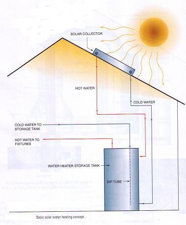
The Operating Principle
Solar Panel and Collector
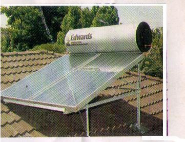
Installation
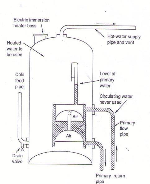
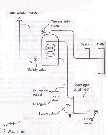
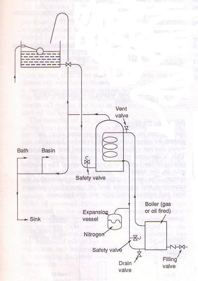
INDIRECT WATER HEATING SYSTEM
In this system, the water that is heated by the boiler is never used out of the hot water faucets but circulates through a heat exchanger. It takes the form of a coil of pipe within the hot water storage tank. The heated water circulates through the system & in turn heats the water held within the storage tank, then returns to the boiler to be reheated.
 The 3 types of Indirect System currently used in buildings are:
Prismatic Cylinder
Calorifiers
Annular Cylinder
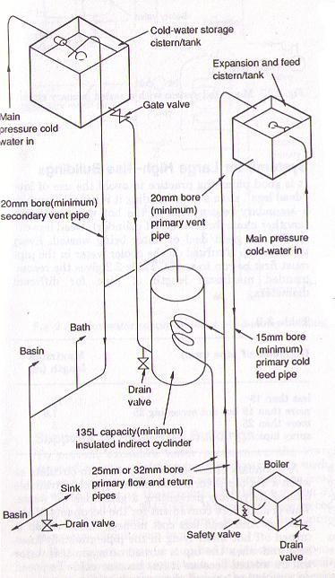
Advantages of Indirect Water Heating System
Since the water in the boiler does not mix with the water in the storage tank, the risk of rusty water being drawn off through the faucets is eliminated.
It keeps the carbonate deposits to a minimum level because once the temporary hardness of the water has been released it will not recur as the same water is reheated over & over again.
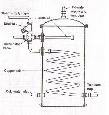
It can use steam as the heating medium instead of water.
Prismatic Cylinder
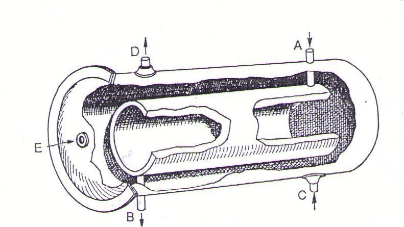
Calorifier
Riser Diagram
Annular Cylinder
HEAT PUMP
Operating Principle
Installation
Equipment
Installation
AVAILABLE TYPES OF HOT – WATER SYSTEM
Localized Water Heating (Single Appliance)
High Pressure
Low Pressure
Centralized Hot Water System
High Pressure
Low Pressure
Storage Water Heaters
High Pressure
Low Pressure
Instantaneous Water Heaters
High Pressure
Low Pressure
CENTRALIZED HOT – WATER SYSTEM
In Centralized System, water is heated & stored centrally and distributed to the hot water faucets via the hot water piping.
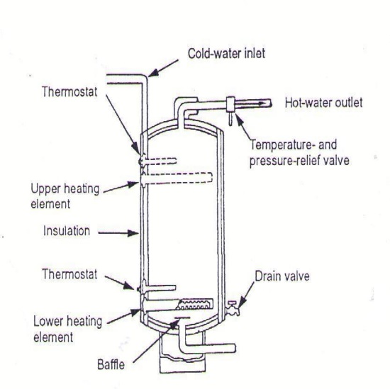
For residences, an electric heating element is directly immersed into the water to be heated.
For commercial & larger projects an independent boiler or furnace is used to heat the water remotely.
The hot water is stored in a Range Boiler or Storage Tank that is located as near the boiler as possible to keep heat losses at a minimum.
Parts of Centralized Hot Water System:
Heating Element / Boiler
The size of the heating element has a direct bearing on the heating up time, which is also related to the size of the storage cylinder. A general guide for adequate supply is:
135 liters = 1500 watts at 60 degrees centigrade in 5 hours & 15 minutes
180 liters = 2000 watts at 60 degrees centigrade in 5 hours & 15 minutes
Thermostat
The key to a satisfactory & economical water heater, automatically switching off the power when the preset temperature is reached & switching on again when hot water is drawn off, or the temperature drops through heat loss. Recommended thermostat settings for average family requirements are 65 to 70 degrees centigrade.
Range Boiler / Hot Water Storage Tank
The hot water tank that serves the domestic hot water system in a storage capacity. The size of the tank depends on the design of the building, the number of occupants and the heating capacity of the supply device. The Storage Tank is a large cylindrical tank at 600 to 1200 mm in diameter & not more than 4500 mm long.
Hot Water Pipes
Should be as short as possible to avoid the use of “Dead Leg”. A “Dead Leg” is a long pipe run whereby it takes a long time to push out the cold water for the sake of a small amount of hot water. The smallest pipe size that will provide a satisfactory flow should be used.
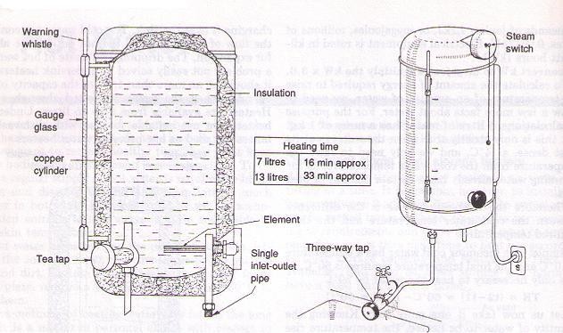
SINGLE BOILING TYPE WATER – HEATER
It is filled with water to the desired level before use. As long as there is a reading on the sight glass the heating element will be covered. The cold - water supply may be from the cold tap by means of a 3-way valve, which supplies cold water to the cylinder or delivers hot water from the cylinder according to the position of the knob. When water boils, steam escapes through a whistle connected into the top of the vessel. The pressure from the steam also turns off the electrical energy to the element if a steam switch is fitted. Boiling water is drawn off through a faucet fitted directly under the heater.
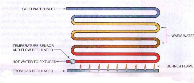
INSTANTANEOUS WATER HEATER
Instantaneous Water Heater instantly heats cold water as it passes through the heater. This heater is compact since storage is not required
Kinds of Model
Shower Model – has a rated power consumption of 6000 watts (6 kW) and provides a continuous supply of hot water at a maximum rate of 3 LPM at a showering temperature of 40 degrees Centigrade.
Lavatory Model – has a rated power consumption of 3000 watts (3kW) & provides a continuous supply of warm water for hand washing at a rate of about 1.4 LPM.
Multi – point Model – serves several fixtures such as lavatory, sink, bidet & shower.
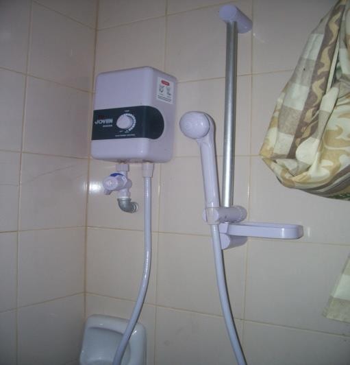
Shower Model of an Instantaneous Water Heater
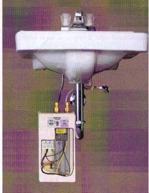
Lavatory Model of an Instantaneous Water – Heater
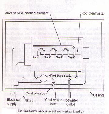
Operating Diagram of an Instantaneous Water – Heater
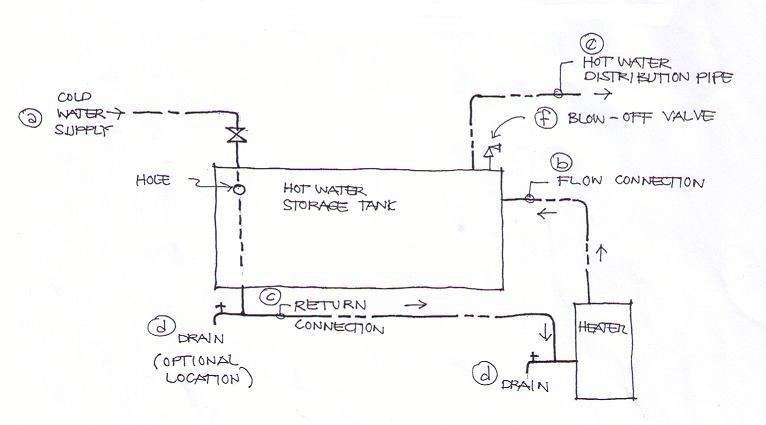
Cold Water Supply
Delivered into the tank via a boiler tube that extends to within 150 mm of the tank bottom. The purpose of this is to avoid the possibility of cooling the hot water which accumulates at the top of the tank. This cold-water line must have a small hole within from the top of the tank. This hole serves as a vacuum breaker & prevents siphonage.
Flow Connection
Connected to an opening on the tank somewhere above its center point. This line is called flow connection because the heated water flows from the heater into the tank.
Return Connection
Connected to a tapping on the bottom of the tank. This line is called the return connection because it returns the colder water from the bottom of the tank to the heater.
Drain Valve
Located at the lowest point of the storage tank.
Hot Water Distribution Pipe
Connected to a tapping on the top of the tank at the point near the flow inlet.
Blow – Off Valve
Installed to the storage tank to control the temperature and pressure and to prevent serious difficulties should the tank become overheated.
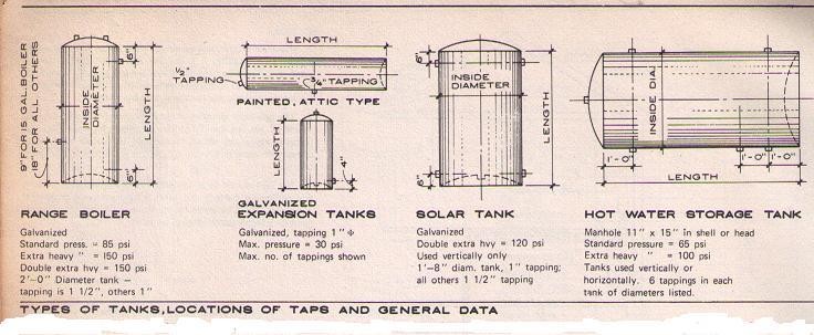
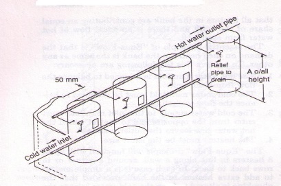
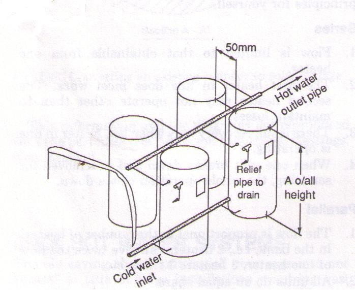
TYPES OF TANKS, LOCATIONS OF TAPS and GENERAL DATA
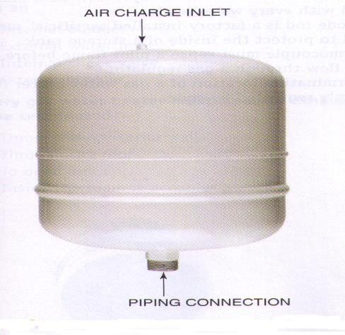
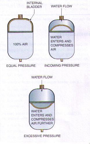 Expansion Tank Operating Principle of Expansion Tank
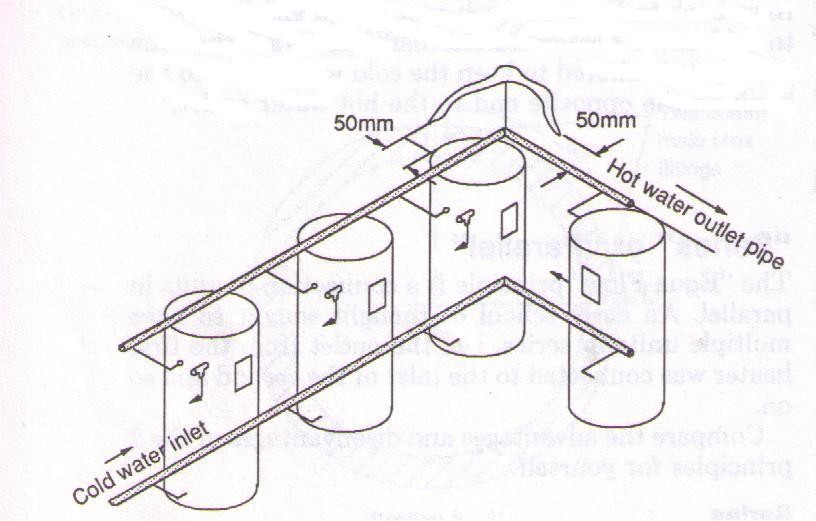
Where large volumes of hot water are required over a short period at constant high temperature to several outlets all being used at one time, one can install 2, 3, 4 or more, quick recovery mains pressure storage heaters in parallel using the “equa flow” manifold. It is designed to ensure that all heaters are contributing.
The essential principle of “Equa – Flow” is that the demand on each heater in the bank is the same as any other.
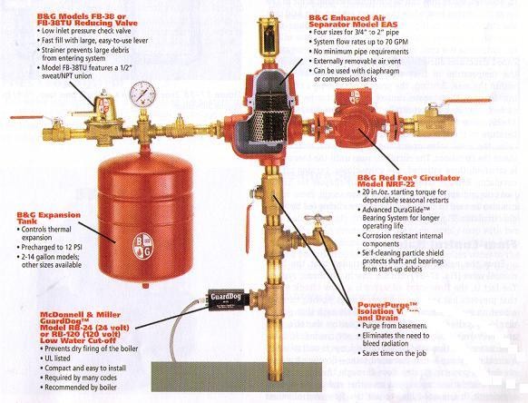
VALVES AND FITTINGS USED IN THE DOMESTIC HOT – WATER SYSTEM
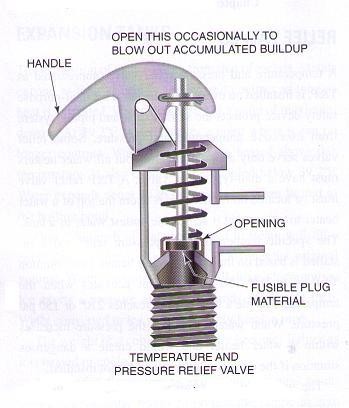
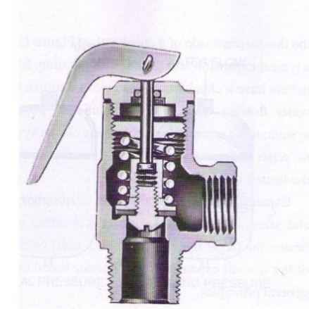
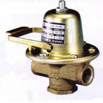
Pressure Relief Valve
It is designed to open if the pressure in the system reaches the set point on the valve. Once the valve opens, the pressure in the system will be relieved and, when the pressure drops to an acceptable level, the valve will close again.
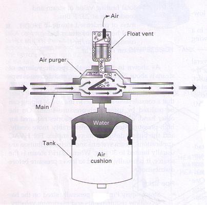
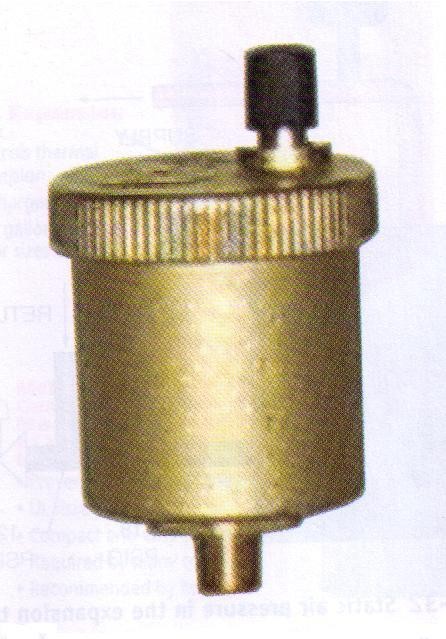
Air Vent – a fitting used to remove air, either manually or automatically, from the hot water heating system.
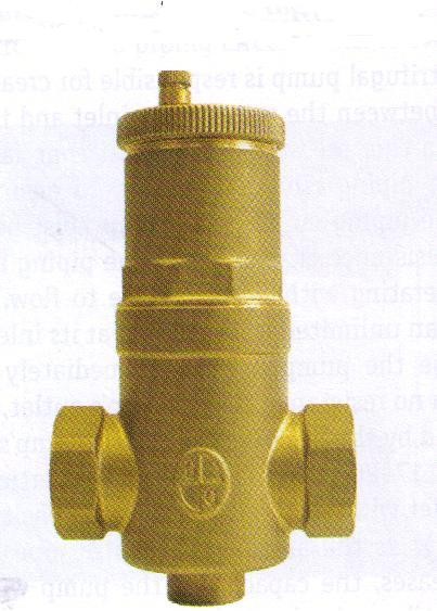 Air Separator – removes smaller air bubbles, called microbubbles, from the system.
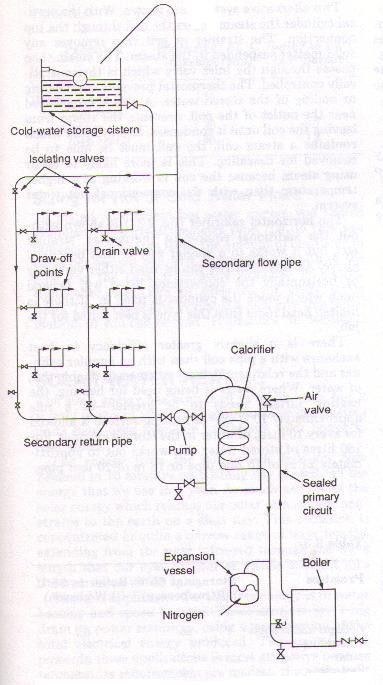
TYPES OF INSTALLATIONS OF HOT – WATER DISTRIBUTION
The installation for hot water distribution consists of the piping work that conveys the heated water from the storage tank to the plumbing fixtures.
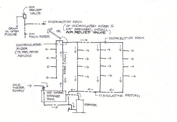
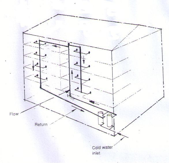
Up - feed and Gravity Return (Recirculation) System – With this system, as the hot water in the pipe cools, the cooled water, being heavier than the hot water, slowly flows down the return pipes to the heaters while the hot water replaces it in the system.
Overhead feed & Gravity Return (Recirculation) System – The operating principle of the overhead system is since in the closed system of piping, water rises when heated. After it has reached the high point of the system, natural forces of gravity return it to the storage unit.
 Pump Circuit System (Pumped Recirculation) – The circulation of hot water to the plumbing fixtures by means of a mechanical device, usually a centrifugal pump. This is used in buildings where the other systems already mentioned are not suitable to produce a circulation of hot water.
Up – feed and Gravity Return System
Commonly used in residential installations.
The purpose of this system is to permit circulation of hot water within the piping arrangement.
The circulating return is economical since it eliminates water waste.
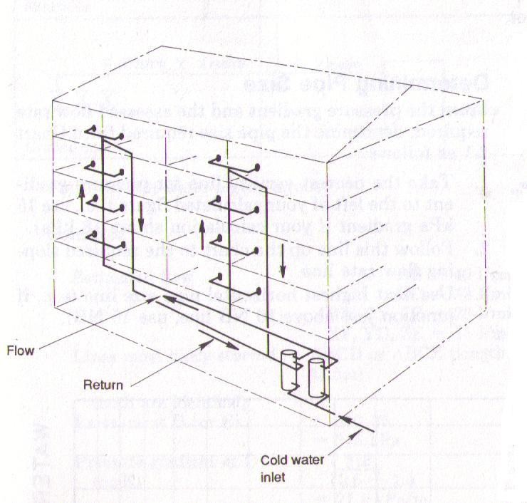
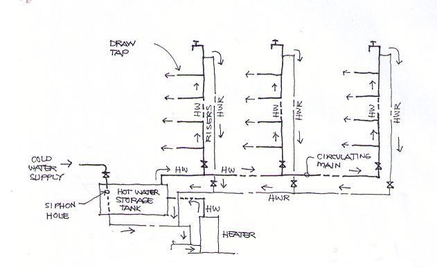
Overhead Feed and Gravity Return System
The most efficient method of delivering hot water to fixtures.
It is generally used in multi-storey buildings
It is dependent on the natural laws governing expansion and gravity.
Its advantage is that it allows continuous circulation even if there is a mechanical defect in the system.
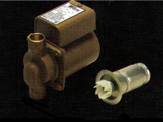
PUMP CIRCUIT SYSTEM
The circulation of hot water to the plumbing fixture by means of a mechanical device, usually a centrifugal pump. The rotary motion of the impeller of the centrifugal pump creates an even movement of hot water in the pipes which makes this pump practical to use.
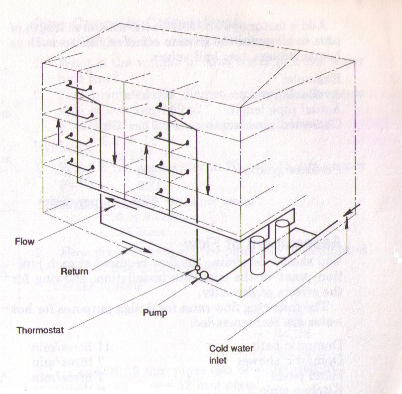
A Circulating Pump moves water through a piping system. Low horsepower pumps are inexpensive to operate
OTHER PIPING LAY – OUTS FOR DOMESTIC HOT – WATER SUPPLY AND DISTRIBUTION
Water Main Feed System
Overhead Tank Feed System
Hot – Water Supply System for a Three – Storey Building
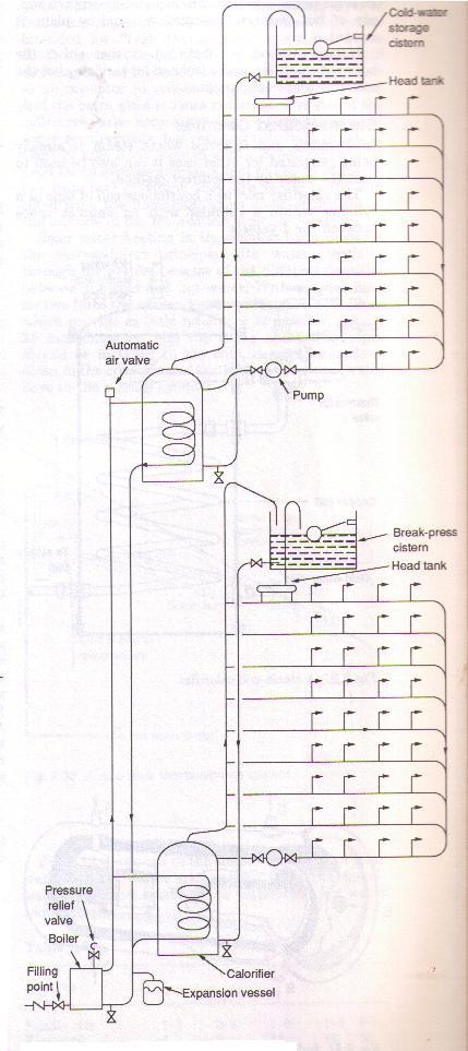
Hot – Water Supply System for a High – Rise Building
SIZING GUIDE FOR CENTRALIZED STORAGE WATER HEATERS (VULCAN BRAND)
Approximately 5 gallons per outlet
OUTLETS | IDEAL GALLONS | VULCAN |
1 BATH or 3 OUTLETS | 15 | 15 |
2 BATHS or 6 OUTLETS | 30 | 24 or 36 |
3 BATHS or 9 OUTLETS | 45 | 45 |
4 BATHS OR 12 OUTLETS | 60 | 71 |
5 BATHS or 15 OUTLETS | 75 | 71 or 90 |
6 BATHS or 18 OUTLETS | 90 | 90 |
7 BATHS or 21 OUTLETS | 105 | 112 |
GALLONS | LITERS | kW RATING At 220 volts | HEIGHT | DIAMETER |
10 | 38 | 3.0 kW | 46 cm | 43 cm |
24 | 90 | 3.0 kW | 94 cm | 44 cm |
36 | 135 | 4.0 kW | 134 cm | 44 cm |
45 | 170 | 4.0 kW | 165 cm | 44 cm |
89 | 340 | 2 x 4.0 kW | 168 cm | 61 cm |
112 | 425 | 2 x 4.0 kW | 188 cm | 65 cm |
CALCULATING DOMESTIC HOT – WATER DEMAND BY THE NUMBER OF FIXTURES
Step 1. Determine the quantity of fixtures that require hot water supply and multiply with the corresponding factor according to type of building served. Refer to Table 1.0
Step 2. Determine the capacity of the heater by solving the probable maximum demand.
Step 3. Determine the storage tank capacity.
Table 1.0 Hot – Water Demand per Fixture (in gallons per hour)
FIXTURE | APART - MENT | CLUB | HOSPITA L | HOTEL | FACTOR Y | OFFIC E | SCHOOL |
Lavatory (private) | 2 | 2 | 2 | 2 | 2 | 2 | 2 |
Lavatory (Public) | 4 | 6 | 6 | 8 | 12 | 6 | 15 |
Bathtub | 20 | 20 | 20 | 20 | 30 | -- | -- |
Dishwasher | 15 | 50-150 | 50-150 | 50-200 | 20-100 | -- | 20-100 |
Kitchen sink | 10 | 20 | 20 | 20 | 20 | -- | 10 |
Laundry tray | 20 | 28 | 28 | 28 | -- | -- | -- |
Pantry sinks | 5 | 10 | 10 | 10 | -- | -- | 10 |
Showers | 30 | 150 | 75 | 75 | 225 | -- | 225 |
Slop sinks | 20 | 20 | 20 | 30 | 20 | 15 | 20 |
DEMAND FACTOR | 0.30 | 0.30 | 0.25 | 0.25 | 0.40 | 0.30 | 0.40 |
STORAGE FACTOR | 1.25 | 0.90 | 0.60 | 0.80 | 1.00 | 2.00 | 1.00 |
EXAMPLE
Determine the heater and storage tank size for an apartment building having the following fixtures.
Item | Quantity |
Basins | 60 |
Bathtubs | 30 |
Showers | 30 |
Kitchen Sinks | 60 |
Laundry Tub | 15 |
SOLUTION
Item | Quantity | Flow/Unit | Total Flow |
Basins | 60 | 2 GPH | 120 GPH |
Bathtubs | 30 | 20 GPH | 600 GPH |
Showers | 30 | 30 GPH | 900 GPH |
Kitchen Sinks | 60 | 10 GPH | 600 GPH |
Laundry Tub | 15 | 20 GPH | 300 GPH |
Possible Maximum Demand | 2520 GPH | ||
 LESSON 7: SEPTIC TANK - DESIGN AND CONSTRUCTION
SEPTIC TANK
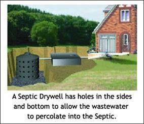
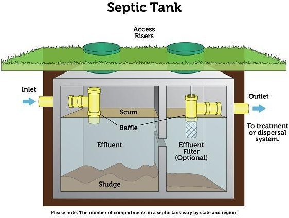 A watertight receptacle which receives the discharge of a sanitary plumbing system or part thereof, designed and constructed to retain solids, digest organic matter through a period of detention and to allow the liquids to discharge into the soil outside of the tank through a system of open – jointed subsurface piping or a seepage pit meeting the requirements of the National Plumbing Code.
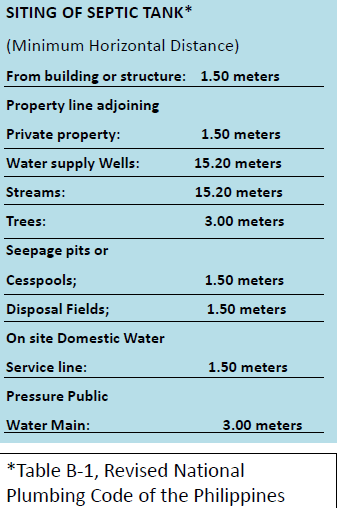
LOCATION OF SEPTIC TANK
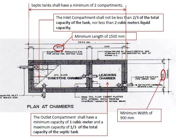
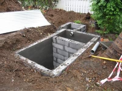
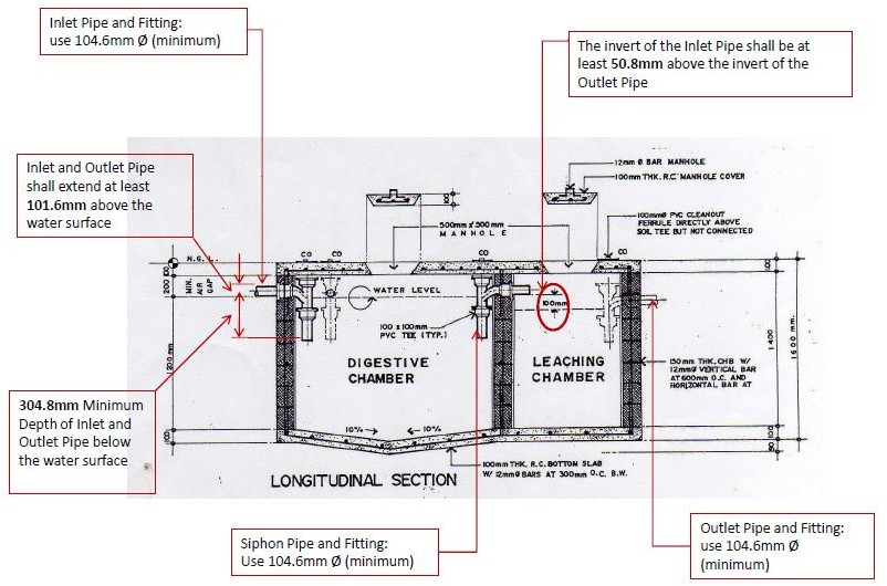
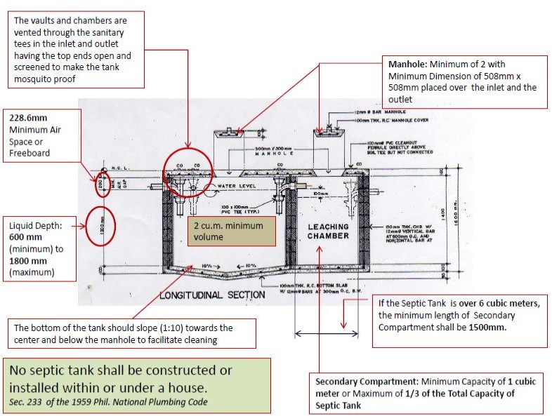 SEPTIC TANK CONSTRUCTION
SIZING OF SEPTIC TANK
Septic tank should be properly sized due to the following conditions:
A septic tank of smaller capacity is impractical because some leeway must be allowed for storage of accumulated sludge.
A tank of larger size is not advisable because retarded bacterial activity is liable to result.
METHOD OF SIZING THE SEPTIC TANK
The Philippine National Plumbing Code of 1959 (Sec. 233) provides the standard sizes of septic tanks based on the capacity (the number of persons) served by the tank.
The 1999 Revised National Plumbing Code of the Philippines uses the Estimated Waste/Sewage Flow Rates of the Design Population in sizing the septic tank. (Tables B-2 and B-3).
If the number of persons served (design population) is not available, the Fixture Unit Method may be employed.
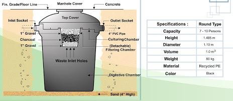 If the values for the estimated waste flow rate are not available, use the following volume: - For residential installations, allow
0.14 to 0.17 cubic meter of tank content per person. - For school, commercial, or industrial purposes, allow 0.06 to 0.09 cubic meter of tank content per person.
CAPACITY OF SEPTIC TANKS
Single Family Dwelling (no. of bedrooms) | Multiple Dwelling Units or Apartments | Other Uses: Maximum DFU Served | Minimum Septic Tank Capacity | ||
Gallons | Liters | m3 | |||
1 or 2 | - | 15 | 750 | 2838 | 2.84 |
3 | - | 20 | 1000 | 3785 | 3.79 |
4 | 2 units | 25 | 1200 | 4582 | 4.58 |
5 or 6 | 3 units | 33 | 1500 | 5677.5 | 5.68 |
- | 4 units | 45 | 2000 | 7570 | 7.57 |
- | 5 units | 55 | 2250 | 8516.3 | 8.52 |
- | 6 units | 60 | 2500 | 9462.5 | 9.46 |
- | 7 units | 70 | 2750 | 10,408.8 | 10.41 |
- | 8 units | 80 | 3000 | 11,355 | 11.36 |
- | 9 units | 90 | 3250 | 12,301.3 | 12.30 |
- | 10 units | 100 | 3500 | 13,247.5 | 13.25 |
Extra Bedroom: 150 gallons (567.8 liters) each | |||||
Extra Dwelling Units over 10: 250 gallons (946.3 liters) | |||||
Extra Fixture Units over 100: 25 gallons (94.6 liters) per fixture unit | |||||
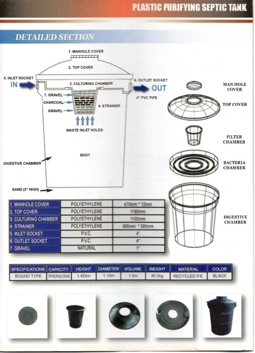
PREFABRICATED SEPTIC TANK
B 5.13.4
Manufactured or prefabricated septic tanks shall comply with all approved applicable standards and be approved by the Administrative Authority.
Independent laboratory tests and engineering calculations certifying the tank capacity and structural stability shall be provided as required by the Administrative Authority.
PRIVATE SEWAGE DISPOSAL SYSTEM

PRIVATE SEWAGE DISPOSAL SYSTEM
A septic tank with the effluent discharging into a subsurface disposal field, seepage pits or of such other facilities as may be permitted by the Plumbing Code.
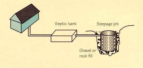
Disposal Field or Sanitary Drain Field
Seepage Pits
Cesspools
DISPOSAL FIELD OR SANITARY DRAIN FIELD
B 6.1 Distribution lines shall be constructed of clay tile laid open joints, perforated clay pipe, perforated bituminous fiber pipe, perforated HDPE pipe, perforated ABS pipe, perforated PVC pipe, or other approved materials, provided that sufficient openings are available for distribution of the effluent into the trench area.
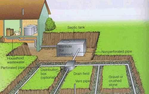
Minimum Spacing of Lines, Center – to – Center is 1.80 m.
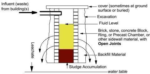
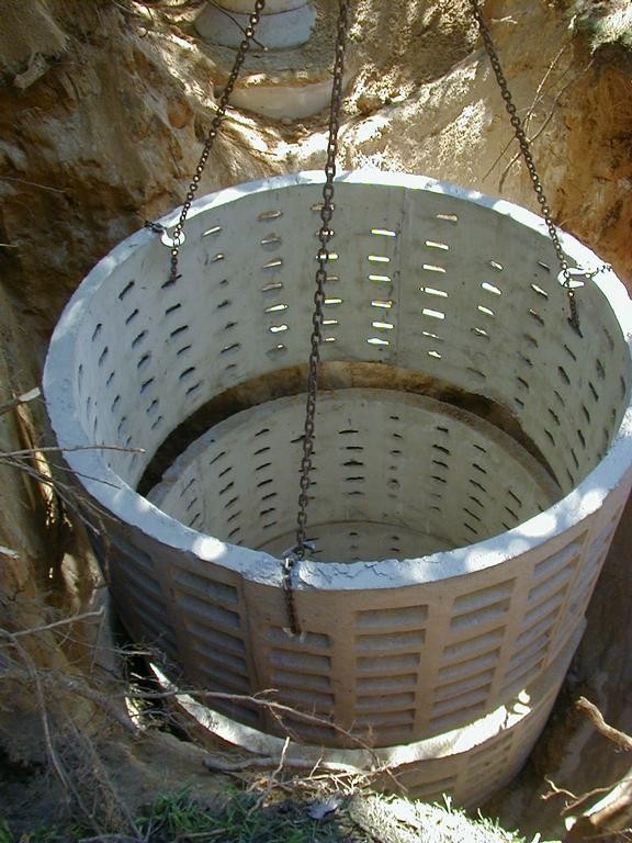
SEEPAGE PITS
Sec. 220.6 A loosely lined excavation in the ground, which receives the discharge of a septic tank and designed to permit the effluent from the septic tank to seep through pit bottom and sides.
B 7.3 Each seepage pit shall be circular in shape and shall have an excavated diameter of not less than 2.20 meters.
CESSPOOLS
Sec. 204.5 A non- watertight lined excavation in the ground which receives the discharge of a sanitary drainage system or part thereof, designed to retain the organic matter and solids discharging therefrom, but permitting the liquid to seep through the bottom and sides of the cesspool.
DESIGN OF SEPTIC TANK (SEWAGE FLOW METHOD)
Determine the estimated sewage flow rates of the occupancy. (Refer to the National Plumbing Code of the Philippines, Table B-3)
Estimated Sewage Flow Rates - Residential | |
Occupancy | Sewage Flow, (lit/day) |
1 bedroom | 600 |
2 bedrooms | 1,200 |
3 bedrooms | 1,600 |
4 bedrooms | 1,900 |
5 bedrooms | 2,200 |
Solve for the volume of the septic tank using the formula.
where:
Vst – volume of septic tank in m3
S – estimated sewage flow in liters/day
Determine the volume of the chamber.
Design the septic tank in terms of the computed volume of the digestive chamber and holding chamber. Assume certain height of the septic tank.
EXAMPLE
1. Design the septic tank for a 2 – storey 3 – bedroom residential house. Assume a depth of septic tank is 1.8 m.
SOLUTION
LESSON 8: MATERIALS FOR DRAINAGE PIPES AND FITTINGS
PIPES AND FITTINGS
Drainage Pipes – are the pipes that convey wastes from the building to an approved point of disposal.
Drainage Fittings – are the pipes accessories in the drainage system, such as coupling, bend, wye, etc., used to join two or more pipes together or to change their direction.
TYPES OF DRAINAGE PIPES
Sanitary or Soil Pipe – the pipe which carries the wastes from water closets, urinals, or fixtures of similar function to the building drain. This contais human excrement.
Waste Pipe – the pipe which carries only liquid wastes, free of human excrement or fecal matter.
Vent Pipe – the pipe connected to the drainage system that conveys air to and from the system and keep the water from being siphned from the trap.
Storm Pipe – the pipe which convey rainwater from the roof gutter to the building storm drain.
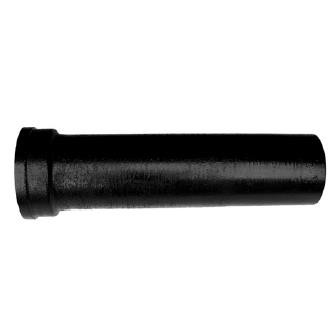
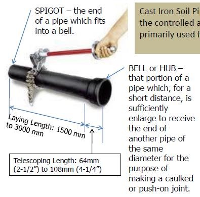
CAST – IRON SOIL PIPE (CISP) – is made from an alloy of iron, carbon, and silicon, with the controlled amounts of manganese, sulfur and phosphorous. This is primarily used for sanitary drain, waste, and storm water systems.
Classification of Cast – Iron Soil Pipe
Class A (100 psi) – Extra Heavy (XH) – is often used for underground applications.
Class B (50 psi) – Service Weight (SV) – is used for general building installations.
Properties of Cast – Iron Soil Pipe
Available Diameter (Nominal I.D.): 2”, 3”, 4”, 5”, 6”, 8”, 12”, and 15”
Length: 1500 mm (5’) and 3000 mm (10’)
Hydrostatic Test: 345 kPa (50 psi) for Service Weight and 690 kPa (100 psi) for Extra Heavy
Most popular and generally specified material for drainage installation. Extensively used in the 60’s and 70’s.
Durable, conveniently installed (< 25 storey)
Commercial Length: 1.5 m and 3.0 m
Affected to some extent by corrosion by acid formed by Carbon Dioxide, Sulphur Oxide, and Methane Gases that create rust.
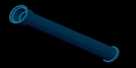
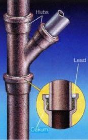
Bell or Hub – is that portion of the pipe which, for a short distance, is sufficiently enlarged to receive the end of another pipe of the same diameter for the purpose of making a caulked or push – on joint. (Section 203.12)
Spigot – is the end of the pipe that fits into a bell. (Section 220.24)
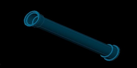
Single Hub – is equipped with 1 hub and 1 spigot end and used in the installation of plumbing in its full length.
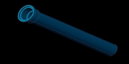
Double Hub – is constructed with hub on each end so it may be cut into 2 pieces when a short piece of pipe is needed.
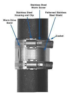
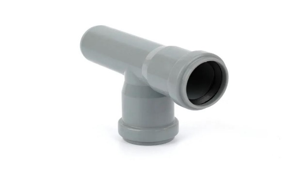
Hubless Pipes – are cast iron pipes with plain ends connected with bolted stainless-steel bands and neoprene gaskets. (Section 209.9)
Single Hb Pipe with Spigot Bead
Single Hub Pipe
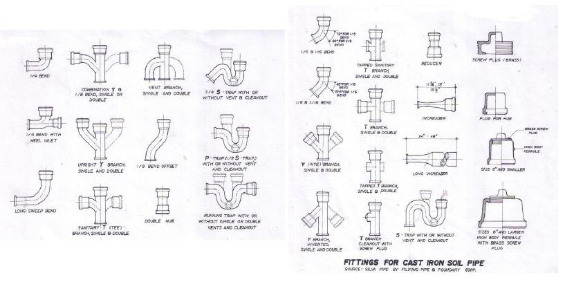
Double Hub Pipe

Hubless Pipe

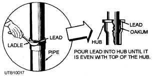
Types of Joints
Caulked joint or calk joint
Stainless Steel Couplings
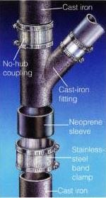
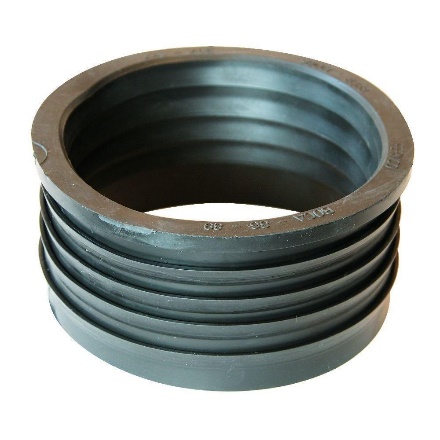
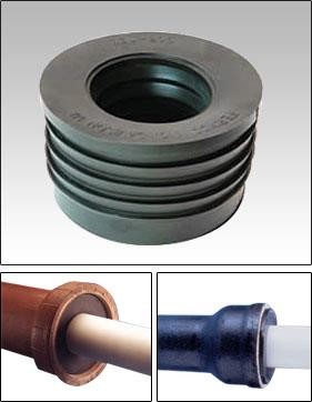
Neoprene Compression Gasket
ABS AND PVC PIPES
ABS and PVC DWV piping installations shall be used in high – rise buildings, provided that its use shall be the discretion of the Master Plumber/ Designer and with the full consent of the owner. (Section 701.1.2)
ABS pipe and fittings are made from a thermoplastic resin called Acrylonitrile – Butadine – Styrene (ABS for short).
A polyvinyl chloride (PVC) pipe is made from a plastic and vinyl combination material.
A PVC pipe does not rust, rot, or wear over time. For that reason, PVC piping is most used in water systems, underground wiring, and sewer lines.
PLUMBING FITTINGS
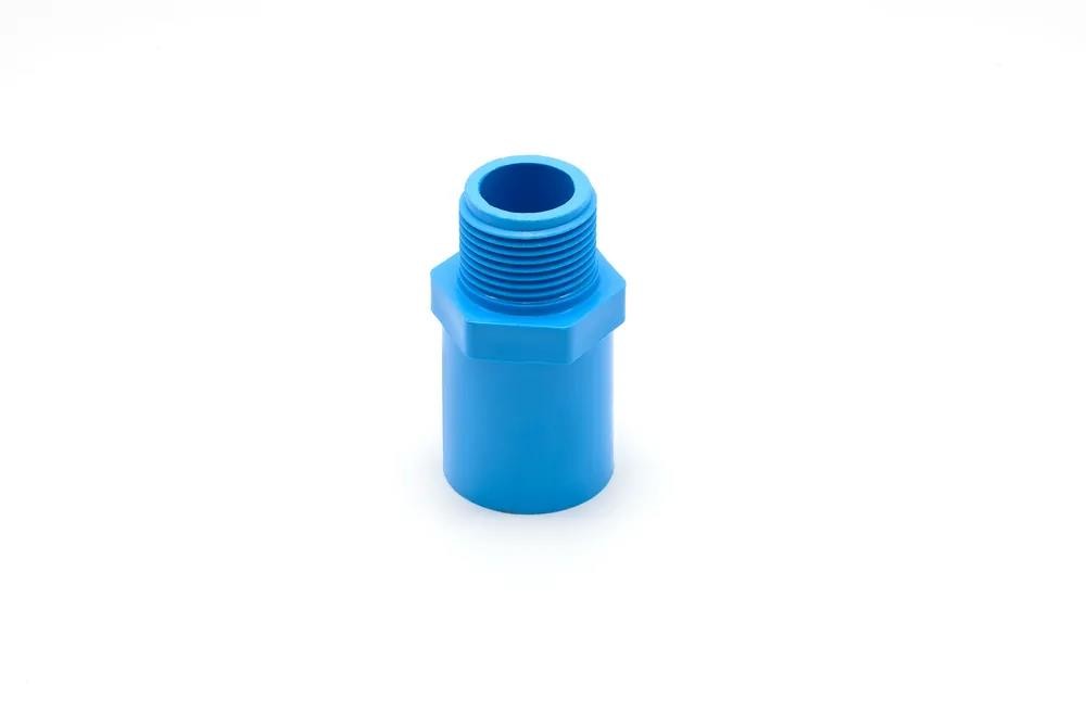
Adapter
An adapter has male and female ends, the male having threads on the outside and the female on the inside.
They are used to connect different sized pipes, or even turn a male pipe into a female and vice versa.
Adapters are essential when it comes to extending or terminating pipe runs.
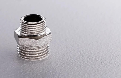
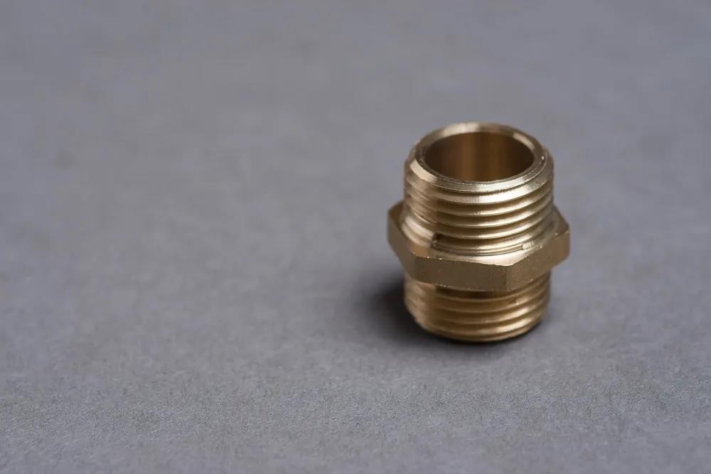
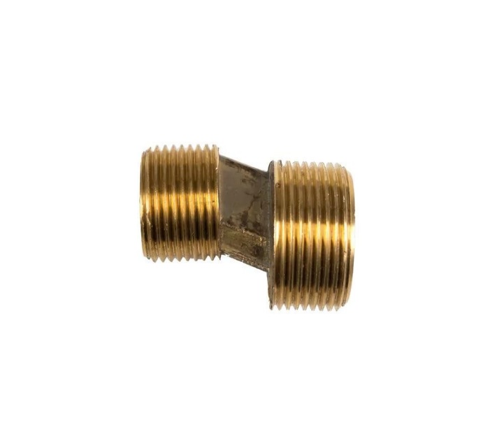
Nipple
A pipe nipple is one of the most popular types of fittings. It connects pipes to appliances such as water heaters and connects two straight pipe runs.
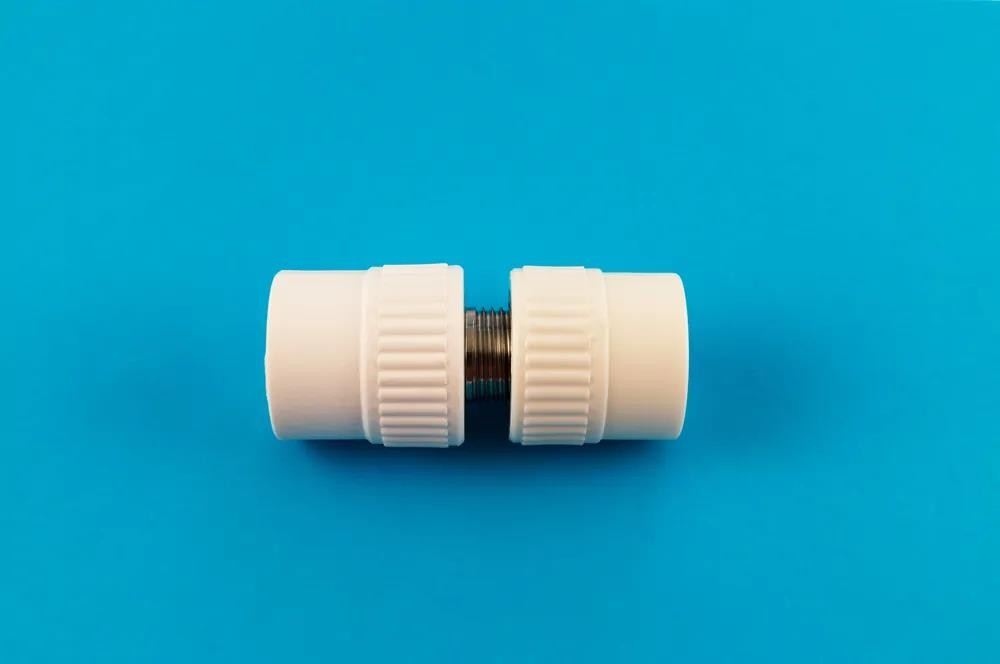
Union
 Union fittings are made up of three parts: a
nut, a female end, and a male end. They are designed to connect two pipes with the possibility of being detached without damage or deformation to the pipes. They are conveniently used in maintenance or cases of planned replacements in the future.
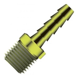
Barb
Barb fittings are generally male at one end and have a tapered and ridged cone at the other. They are designed to grip the inside of a tube and seal the connection.
As the arb fitting is inserted, the hose or tube will first expand and then relax. When the tube or hose relaxes and goes back to its original size, the connection is sealed and becomes difficult to undo. Barbed fittings are generally used in gas, air, and fluid control applications in low pressure.
Coupling
Couplings are very similar to unions. However, these cannot be detached without damage to the pipes.
Couplings can be used to connect two pipes of the same size and diameter. They are also commonly used to change pipe sizes; a bell reducer is a common coupling used to do this since it connects a big pipe to a smaller one.
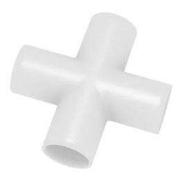
Cross
As the name might suggest, crosses are four – way fittings, a combination of two tees. They consist of one inlet and three outlets, and these often have a solvent – welded socket or female – threaded ends.
Cross fittings are not as popular as tees. The reason being that they can stress pipes as temperature changes due to the four open ways.
Crosses are mostly used in plumbing where thermal expansion is not an issue, such as fire sprinkler systems.
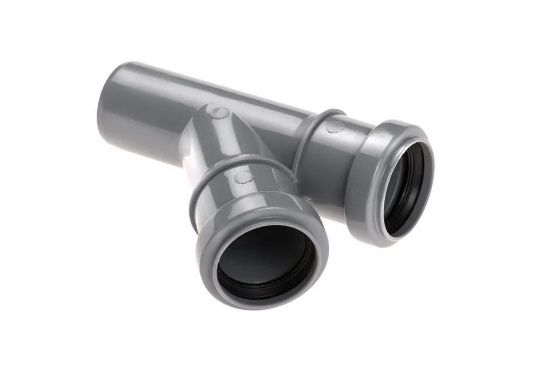
Tees
Tees are a three-way fitting. They look like a coupling with an outlet in the middle. They are short pipes with a 90- degree “branch” at the center.
There are two main types of tees:
Straight tee: Used in setups where the pipe run is the same size as the tee branch.
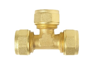 Reducing tee: Used where the tee branch is smaller than the run pipe.
Saddle Tee
Saddle tees look very similar to a real saddle. They are only available in PVC and used to add a tee to an existing pipe without the need to cut or resolder.
 These are most often used in irrigation systems when you need to add a new sprinkler line. Saddle tees are snapped onto the pipe using glue. Once the glue is settled, a new hole is drilled.
Wye
Wyes look like the letter “Y”. They are generally used in drainage fittings and have a 45 – degree branch.
The angling of the branch is designed to reduce the turbulence and friction. They connect vertical drainpipes to horizontal ones.
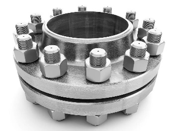
Flanges
A flange is a round fitting used to connect pipes. The pipes are either threaded or welded to the middle of the flange, and then sealed together. The holes on the outside are used for bolts.
Flanges are mainly used in industrial applications due to their ability to handle high pressure. You can also find flanges in residential pump systems.
Elbows
Elbow fittings are curved and mainly used to change flow directions. These are mostly produced in 45 and – degree angles and can be sweated or threaded.
The ends of the elbow fitting can be made for butt welding, threading or socketed. A reducing elbow is when the two ends differ in size.

Caps
Caps are used to cover the end of an open pipe and are liquid and gas tight. The cap can be attached to the pipe end by interior threading or solvent welded socket.
The outside of a cap can be square, round, rectangular, I – or U – shaped; some will even have a handgrip.
Plugs
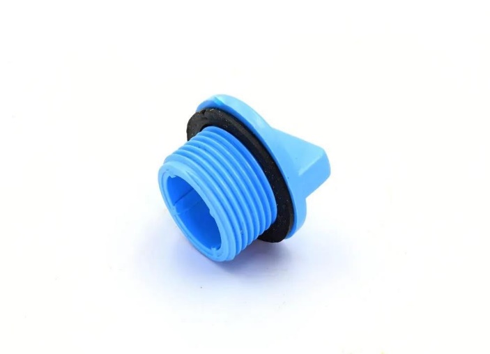 Plugs are used similarly to caps, but instead of being fitted on the pipe, they are fitted inside. These are usually threaded to allow the plug to be removed for future use of the pipe.
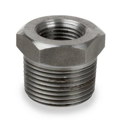
Bushings
Brushings look like small screws. They are mainly used to connect pipes of different sizes, reducing a large fitting of a small pipe. These can be threaded on the inside and outside; however, this is not always the case.
Brushing fittings are smaller than unions and couplings, and are, therefore, often used in the same situations.
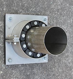
Mechanical Sleeve
A mechanical sleeve joins two pipes using a screw or other device and is easy to install.
The sleeve is usually made of rubber and is inserted into a stainless-steel clamp. The clamp compresses the rubber, which creates a tight seal.
This type of fitting is slightly flexible and can be used in misalignments in difficult places.
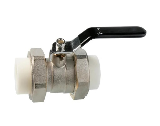
Valve
A valve is used to regulate or stop the flow of gas or liquid. Valves are generally categorized by application, such as:
Isolation: Used to disconnect a part of a piping system temporarily. Usually left fully open or closed and can be in place for years before replacement.
Throttling: Used to control the pressure of a fluid. Designed to withstand wear and stress; however, they might eventually give in. Usually installed along with an isolation valve in case of malfunction.
Non – return: Also called check valves, these allow a free flow of fluids in one direction but prevents reverse flow. Often used in sewage and drainage systems.
Reducer
A reducer is designed to reduce flow. It comes in two types:
Concentric reducer: Looks like a cone. Designed to join two pipe sections on the same axis. Usually used when there is a change in pipe diameter.
Eccentric reducer: Used in piping systems where the upstream pipe is larger than the downstream pipe.
Clean – Outs
A clean – out fitting features removable parts that allow access to drains without the need to undo plumbing fixtures. Clean – outs will enable an auger (a type of drill) to enter and clean a clogged drain.
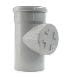 Its crucial clean – outs are placed in accessible locations since an auger is not the longest tool. Larger plumbing systems feature several clean – outs that will be placed at regular intervals.
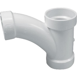
Combo Tee
Combination tees have a gradually curving central branch. They are used in drains to give a smooth, slightly curving path to reduce the chances of clogs. The curve also makes it easier for a plumber to push a snake tool through.
Diverter Tee
This type of tee is mainly used in pressurized hydronic heating systems. It diverts portions of the flow from the primary line into a side branch that is connected to a heat exchanger.
It is designed to allow a regular flow through the main line, even if the branch is shut off.
LESSON 9. FIRE FIGHTING AND FIRE SUPRESSION SYSTEMS
FIRE – is a complete set of chemical reactions in which fuel combines with oxygen and an ignition source to produce heat.
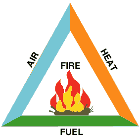
THREE ELEMENTS REQUIRED TO START A FIRE
Fuel
Oxygen
Heat
Note: The oxidation process will not be possible without any one of these elements.
THE FIRE TRIANGLE


DYNAMICS OF FIRE
Four Stages of Fire Development
Incipient
The first stage begins when heat, oxygen and a fuel source combine and have a chemical reaction resulting in fire. This is also known as “ignition” and is usually represented by a very small fire which often (and hopefully) goes out on its own, before the following stages are reached. Recognizing a fire in this stage provides your best chance at suppression or escape.
Growth
The growth stage is where the structures fire load and oxygen are used as fuel for the fire. There are numerous factors affecting the growth stage including where the fire started, what combustibles are near it, ceiling height and the potential for thermal layering. It is during this shortest of the 4 stages when a deadly flashover can occur: potentially trapping, injuring, or killing firefighters.
Fully Developed
When the growth stage has reached its maximum and all combustible materials have been ignited, a fire is considered fully developed. This is the hottest phase of a fire and the most dangerous for anybody trapped within.
Decay
Usually, the longest stage of a fire, the decay stage is characterized a significant decrease in oxygen or fuel, putting an end to the fire. Two common dangers during this stage are first – the existence of non – flaming combustibles, which can potentially start a new fire if not fully extinguished. Second, there is the danger of a backdraft when oxygen is reintroduced to a volatile, confined space.
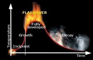
Flashover – is not a stage of development, but simply a rapid transition between the growth and fully developed stages.
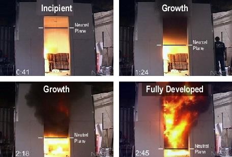
Note: The interface of the hot and cold gas layers at an opening is commonly referred to as the neutral plane.
AIMS IN FIRE SAFETY DESIGN
To prevent fire
To safeguard the lives of occupants and firefighters
To reduce damage on the building, its contents, and on surrounding buildings.
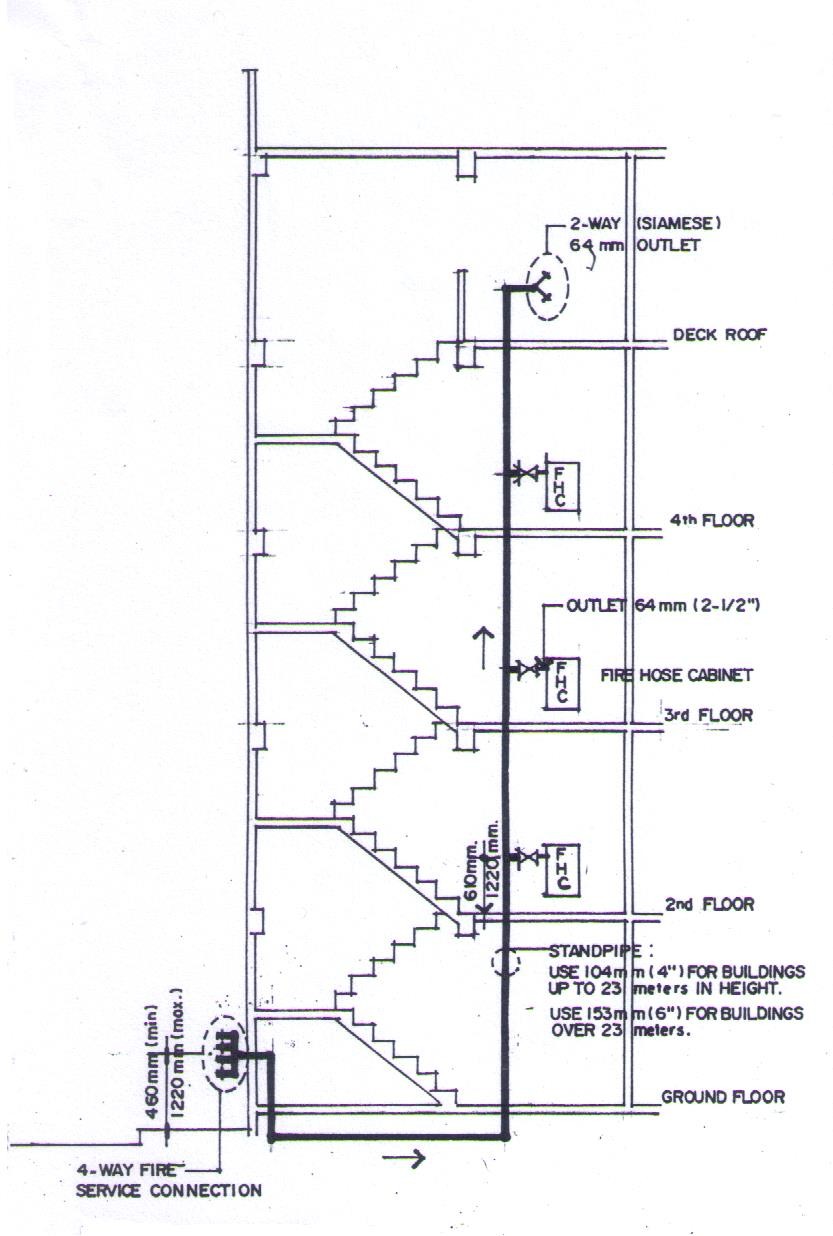
STANDPIPES
Section 10.2.6.6 Standpipes
The design, installation and maintenance of Standpipes Systems shall be in accordance with NFPA 14, Standard for the Installation of Standpipe, Private Hydrant and Hose Systems.
Classes of Standpipe Systems
Class I System
Class II System
Class III System
CLASS SYSTEM
A standpipe system shall be any of the following:
a. Class I System.
This system is provided with 64mm (2 ½ in.) hose connections for full – scale firefighting at the following designated building locations:
At each intermediate landing between floor levels in every required exit stairway.
On each side of the wall adjacent to the exit openings of horizontal exits.
In each exit passageway at the entrance from the building areas into the passageway.
In covered mall buildings, at the entrance to each exit passageway or exit corridor, and at exterior public entrances to the mall.
At the highest landing of stairways with stairway access to a roof and on the roof where stairways do not access the roof. An additional 64 mm (2 ½ in) hose connection shall be provided at the hydraulically most remote riser to facilitate testing of the system.
Where the most remote portion of a no sprinklered floor or storey is located in excess of 40 meters of travel distance from a required exit containing or adjacent to a hose connection, or the most remote portion of a sprinklered floor or storey is located in excess of 61 meters of travel distance from a required exit containing or adjacent to a hose connection, additional hose connections shall be provided, in approved locations, where required by the BFP.
b. Class II System
This a hose connection provided with 38 mm (1 ½ in.) hose or within thirty-seven meters (37 m) of a hose connection system shall be provided with 38 mm (1 ½ in.) hose connections for first aid firefighting, so that all portions of each floor level of the building are within forty meters (40 m) of provided with less 38 mm (1 ½ in.) hose.
Distances shall be measured along a path of travel originating at the hose connection.
c. Class III System
This system shall be provided with hose connections as required for both Class I and Class II systems.
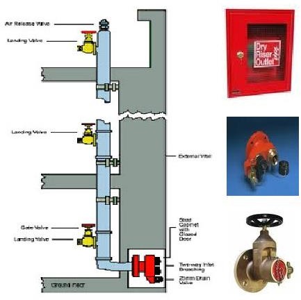
Dry Standpipe
A type of standpipe system in which the pipes are normally not filled with water. Water is introduced into the system thru fire service connections when needed.
Notes:
Dry standpipes shall not be concealed in building walls or built into pilasters. Portions of dry standpipes systems not located within an enclosed stairway or smokeproof enclosure shall be protected by a degree of fire resistance equal to that required for vertical enclosures in the building in which they are located.
An approved durable sign with raised letters of at least twenty-five millimeters (25 mm) in height shall be permanently attached to all fire service street connections, cast on a plate or fitting that reads “DRY STANDPIPE”. A sign indicating the pressure required at the inlets to deliver the system demand shall also be provided.
Fire service connections shall be in the street side of the buildings, fully visible and recognizable from the street or nearest point of fire apparatus accessibility. And shall be located and arranged so that hose lines can be attached to the inlets without interference from nearby objects, including buildings, fences, posts, or other fire service connections.
All buildings with required enclosed stairway or smokeproof enclosure shall have at least one dry standpipe outlet connection located at every floor level landing above the first floor of every required enclosure. No point within a building, requiring dry standpipes, shall be more than forty meters (40 m) travel distance from a dry standpoint outlet connection.
Fittings and connections shall be of sufficient strength to withstand 300 psi (21 kg/cm2) of water pressure when ready for service. All dry standpipes shall be tested hydrostatically to withstand not less than 50 psi (3.5 kg/cm²) above the maximum working pressure.
Wet Standpipe
It is an auxiliary fire line system with a constant water supply installed primarily for emergency use by the occupants of the building.
Wet standpipe system extending from the cellar or basement into the topmost storey shall be required in the following:
Assembly occupancies with an occupant load exceeding one thousand (1,000).
Educational, healthcare and detention and correctional, business, and mercantile, industrial, and hotels and apartments occupancies, four or more storeys in height.
Hazardous storage and business and mercantile occupancies having a floor area exceeding one thousand eight hundred sixty square meters (1,860 m2) per floor.
Wet standpipes shall be located so that all portions of the buildings are within six meters (6 m) of a nozzle attached to twenty-two meters (22m) of hose.
The size of the standpipes shall not be less than 64 mm (2 ½ in.) in diameter.
Each wet standpipe outlet shall be supplied with a hose not less than thirty-eight millimeters (38 mm) in diameter. Such hose shall be equipped with an approved variable for nozzle. An approved hose reel rack or cabinet shall be provided and shall be located to make the hose accessible.
The hose reel rack or cabinet shall be recessed in the wall or protected by suitable cabinet
Wet standpipe system may be supplied from a sprinkler system only when in compliance with NFPA 13, Standard for the Installation of Sprinkler System.
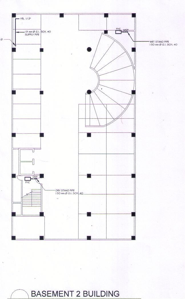
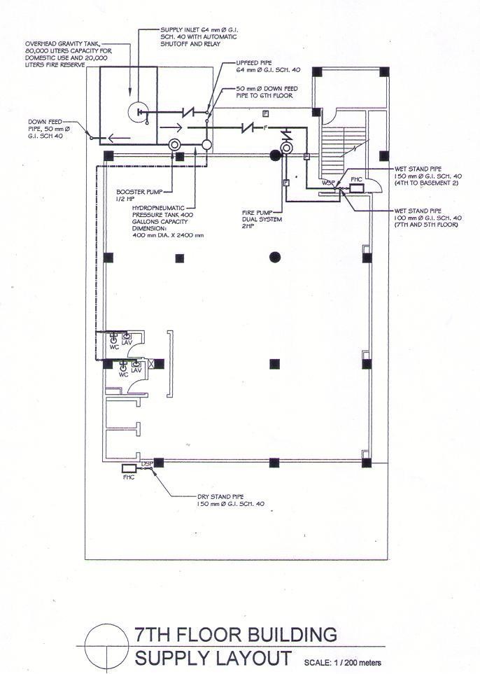
Fire pumps shall be approved and shall deliver not less than the required fire flow and pressure. Such pumps shall be supplied with adequate power source and shall be automatic in operation.
Where the wet standpipe system is supplied with water from the domestic supply of building, approved fire pumps shall not be required provided the domestic pump used delivers the required fire flow.
All horizontal runs of dry standpipe systems shall have a twenty percent (20%) slope for the purpose of draining. Where pipe traps occur in such standpipes systems including fire service connections, they shall be provided with drains. Piping’s shall not pass through hazardous areas and shall be located so that it is protected from mechanical and fire damage.
PRESSURIZATION – technique whereby air is blown into spaces which are designed to be kept clear of smoke.
Uses barriers including walls, floors, and doors, to contain pressurized air generated by mechanical means to keep smoke away from protected areas such as escape staircases and corridors.
Blower
Each standpipe shall be equipped with an approved sixty-four millimeters (64 mm) outlet not less than sixty-one centimeters (61 cm) nor more than one hundred twenty-two centimeters (122 cm) above the floor of each storey.
All one hundred two millimeters (102 mm) dry standpipes shall be equipped with a four-way fire service connection. All fire service connections shall be located on a street front, not less than forty-six centimeters (46 cm) or more than one hundred twenty-two centimeters (122 cm) above grade and shall be equipped with an approved straight way check valve and substantial plugs or caps.
All fire service connections shall be protected against mechanical injury and shall be visible and accessible. More than one fire service connection may be required.
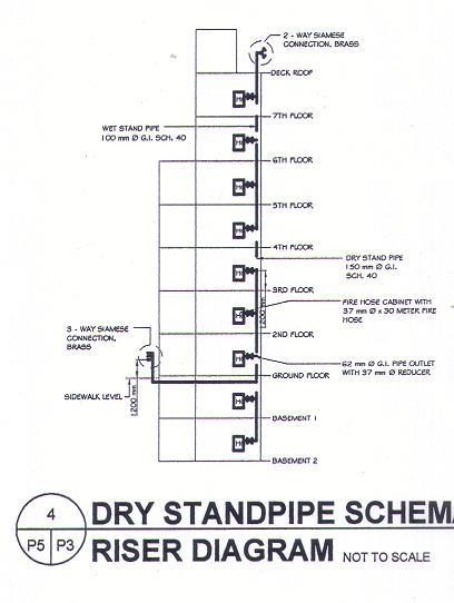
All dry standpipes shall be equipped with a two-way sixty-four millimeters (64 mm) outlet above the roof line of the building when the roof has a slope of less than thirty centimeters (30cm) long wrench may be used in connecting the hose with clearance for the wrench on all sides of the outlet.
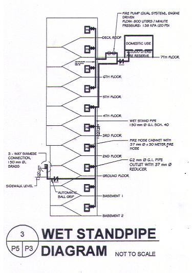
1.8 kg/cm² = 26 psi or
176 kPa
The wet standpipe shall deliver not less than one hundred thirty-two liters (132 ℓ) of water per minute at not less than one and eight- tenths (1.8) kilograms per square centimeter residual pressures from each of any two outlets flowing simultaneously for thirty (30) minutes.
Pressure or gravity tanks shall have a capacity sufficient to furnish at least two hundred sixty-five (265) liters of water per minute for thirty (30) minutes. Other such tanks shall be located to provide not less than one and eight-tenths (1.8) kilograms per square centimeter residual pressure from each of two (2) outlets flowing simultaneously for thirty (30) minutes.
7,950 liters
All interior wet standpipes shall be equipped with thirty-eight millimeters (38 mm) valve in each storey, including the basement or cell roof of the building and located not less than ninety-one centimeters (91cm) nor more than one hundred eighty-two centimeters (182 cm) above the floor.
Combination Standpipe
A pipeline system filled with water and connected to a constant water supply for the use of the BFP and the occupants of the buildings
solely for fire suppression purposes
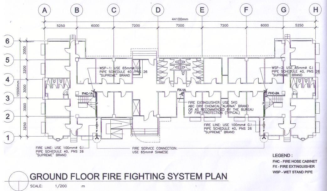
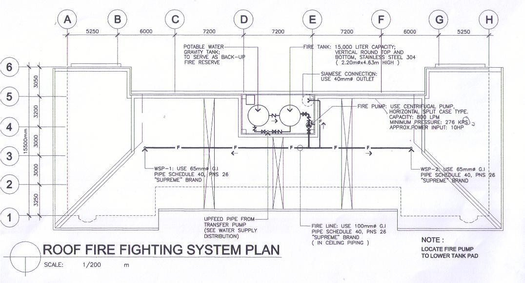
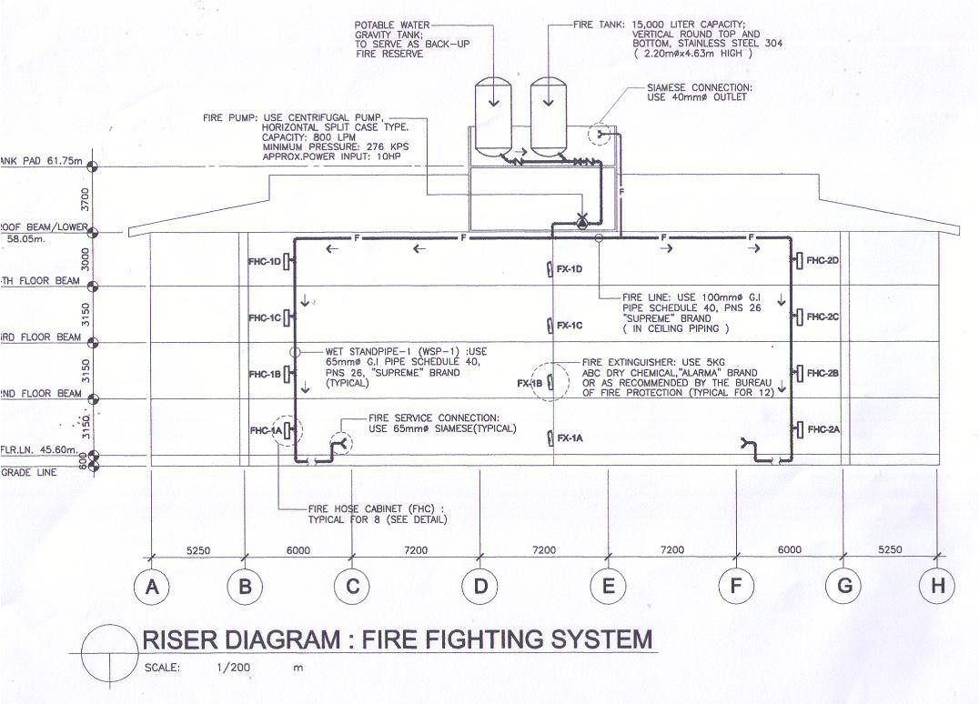
Fire Department House Connection – is a hose connection at grade or street level for use by the Fire Service only. It is also known as Fire Service Connection.
FIRE EXTINGUISHER
TYPES OF FIRE
Class A. Ordinary Combustibles: wood, paper, cloth, trash, and other ordinary materials.

Class B. Flammable Liquids and Gases: gasoline, oils, paint lacquer and tar.

Class B. Flammable Liquids and Gases: gasoline, oils, paint lacquer and tar.

Class C. Fires involving live electrical equipment.

Class D. Combustible Metals or Combustible Metal Alloys

Portable fire extinguishers are classified for use on certain classes of fires and rated for relative extinguishing effectiveness as determined by the Bureau of Product Standard, Department of Trade and Industry.
RATING OF FIRE EXTINGUISHERS
Class A Extinguishers will put out fires in ordinary combustibles such as wood and paper. The numerical rating for this class of fire extinguisher refers to the amount of water the fire extinguisher holds and the amount of fire it will extinguish.
Class B Extinguishers should be used on fires involving flammable liquids, such as grease, gasoline, oil, etc. The numerical rating for this class of fire extinguisher states the approximate number of square feet of a flammable liquid fire that a non – expert person can expect to extinguish.
Class C Extinguishers are suitable for use on electrically energized fires. This class of fire extinguishers does not have a numerical rating. The presence of the letter “C” indicates that the extinguishing agent is non – conductive.
Class D Extinguishers are designed for use on flammable metals and are often specific for the type of metal in question. There is no picture designator of Class D extinguishers. These extinguishers generally have no rating nor are they given a multi – purpose rating for use on other types of fires.
The classification of fire extinguishers shall consist of a letter that indicates the class of fire on which a fire extinguisher has been found to be effective, preceded by a rating number (Class A and Class B only) that indicates the relative extinguishing effectiveness, except for fire extinguishers classified for use on Class C, Class D hazards shall not be required to have a number preceding the classification letter.
The following types of fire extinguishers are considered obsolete and shall be removed from service:
Soda acid
Chemical foam (excluding film – forming agents)
Vaporizing liquid (carbon tetrachloride)
Cartridge – operated water
Cartridge – operated loaded stream
Copper or brass shell (excluding pump tanks) joined by soft solder or rivets.
TYPES OF FIRE EXTINGUISHERS
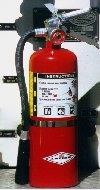 Dry Chemical extinguishers are usually rated for multiple purpose use. They contain an extinguishing agent and use a compressed, non-flammable gas as a propellant.
Halon extinguishers contain a gas that interrupts the chemical reaction that takes place when fuels burn. These types of extinguishers are often used to protect valuable electrical equipment since they leave no residue to clean up. Halon extinguishers have a limited range, usually 1.2 to 1.8 meters. The initial application of Halon should be made at the base of the fire, even after the flames have been extinguished.
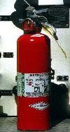
Carbon Dioxide (CO2) extinguishers are most effective on Class B and C (liquids and electrical) fires. Since the gas disperses quickly, these extinguishers are only effective from 1.0 to 2.4 feet. The carbon dioxide is stored as a compressed liquid in the extinguisher; as it expands, it cools the surrounding air. The cooling will often cause ice to form around the “horn” where the gas is expelled from the extinguisher. Since the fire could re-ignite, continue to apply the agent even after the fire appears to be out.
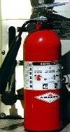
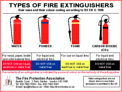
SELECTION OF FIRE EXTINGUISHERS BY HAZARD
1. Fire extinguishers shall be selected for the classes of hazards to be protected.
i. Fire extinguishers for protecting Class A hazards shall be selected from the following:
Water type
Multi – purpose dry chemical type
Wet chemical type
ii. Fire extinguishers for protection of Class B hazard shall be selected from the following.
Aqueous film – forming foam (AFFF)
Fil – foaming fluoroprotein foam (FFFP)
Carbon dioxide
Dry chemical type
Rooms or areas shall be classified as:
Light (low) hazard
Ordinary (moderate) hazard
Extra (high) hazard
Limited areas of greater or lesser hazard shall be protected as required.
SIZE AND PLACEMENT OF FIRE EXTINGUISHERS
Fire Extinguishers for Different Types of Class A Hazard
Type of Hazard | Minimum Extinguisher Rating | Maximum Travel Distance to Extinguisher | Maximum Area (Open Area) per Extinguisher |
Low | 2 – A | 15 meters | 200 square meters |
Moderate | 3 – A | 12 meters | 100 square meters |
High | 4 – A | 10 meters | 75 square meters |
Fire Extinguishers for Different Types of Class B Hazard
Type of Hazard | Minimum Extinguisher Rating | Maximum Travel Distance to Extinguisher | Maximum Area (Open Area) per Extinguisher |
Low | 5 – B | 10 meters | 200 square meters |
Moderate | 10 – B | 10 meters | 100 square meters |
High | 40 – B | 10 meters | 75 square meters |
HOW MUCH FIRE WILL YOUR EXTINGUISHER HANDLE?
To achieve a Class A rating, the extinguisher must be capable of putting out the wood crib, wood panel and excelsior (shredded paper) tests. Ratings are based on the size of the material that can be repeatedly extinguished.
Rating | Wood Crib, in | Wood Panel, ft | Excelsior, lbs |
1 – A | 20 x 20 x 20 | 8 x 8 | 6 |
2 – A | 25 x 26 x 26 | 10 x 10 | 12 |
3 – A | 30 x 30 x 30 | 12 x 12 | 18 |
4 – A | 33 x 30 x 30 | 14 x 14 | 24 |
6 – A | 38 x 38 x 38 | 17 x 17 | 36 |
10 – A | 48 x 48 x 48 | 17 x 17 | 36 |
To achieve a Class B rating, the extinguisher must repeatedly put out a flaming liquid fire. Ratings are based on the size of the fire.
Rating | Pan Size (sq.ft) | Gallons of Heptane |
1 – B | 2.5 | 3.25 |
2 – B | 5.0 | 6.25 |
5 – B | 12.5 | 15.5 |
10 – B | 25.0 | 31.0 |
20 – B | 50.0 | 65.0 |
30 – B | 75.0 | 95.0 |
40 – B | 100.0 | 125.0 |
HEPTANE
A volatile, colorless, highly flammable liquid hydrocarbon, C7H16, obtained in the fractional distillation of petroleum and used as a standard in determining octane ratings, as an anesthetic, and as a solvent.