
10. MR Physics & Imaging
Introduction
MRI is non-ionizing
MRI can have both anatomical and functional imaging
MRI uses precession imaging
NMR is nuclear magnetic resonance, but is not related to radioactive decay (the nucleus is spinning, but there’s no radioactivity)
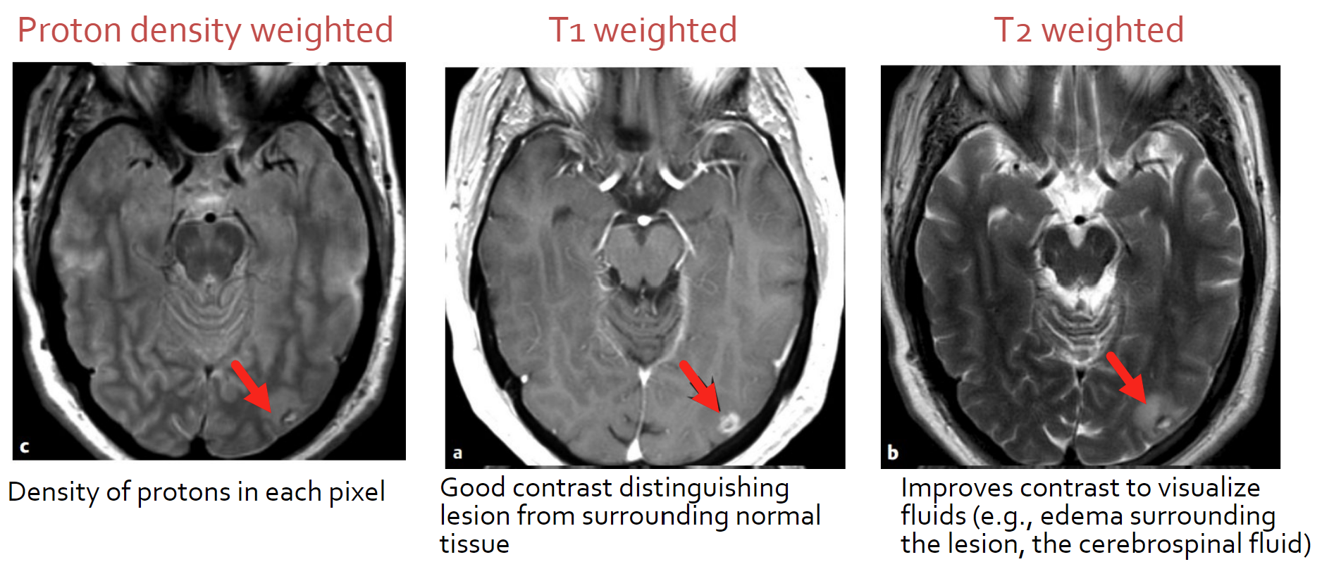
MRI offers images of the same object in different contrasts to bring attention to different areas
Physics
Protons and neutrons are spinning inside the atom, which act like magnets
Spinning nuclei in an atom must have an odd atomic number or odd mass number to exhibit this behavior
If a nuclei has an even atomic number, the magnetic fields cancel out
Spinning nuclei possess angular momentum (J) called spin
Placed in a magnetic field, the spin of the protons and neutrons assume certain orientations
Each spin produces a microscopic magnetization vector (𝜇)
𝜇 = 𝛾 * J where gamma is the gyromagnetic ratio (specific to each material)
Gyromagnetic ratio gamma is radians per second*Teslas
The gyromagnetic ratio can also be gamma divided by 2pi
The body is mostly water, which has a lot of hydrogen and is a great source for MRI signal
Hydrogen has the highest gyromagnetic ratio
The net (macroscopic) magnetization of a magnetic field is zero in its natural state
A single particle will have its own nonzero magnetic field
Bulk Magnetization Vector
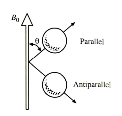
Once an external magnetic field (B0) is applied…
The spins of each particle align in parallel or anti-parallel (a semi majority in parallel)
The net (bulk) magnetization vector with an external magnetic field is nonzero
The bulk magnetization (𝜇 vector) vector is the source of the MR signal (also called M vector)
B0 is always applied along the z direction (up-down on the body)
Field strengths in MRI are commonly 1.5 T or 3 T (Tesla)
A 1.5T magnet is about 30,000 times stronger than Earth’s magnetic field
RF cage has to be in the MRI room to absorb any signals from outside, otherwise FM radio frequencies would be measured
The vector 𝜇 precesses (spins) around the z axis st an angular frequency 𝜔 (radians per second)
𝜔0 = 𝛾 * B0
Larmor Frequency: The angular frequency at which the bulk magnetization factor precesses around the z-axis
f = 𝛾 / (2pi) * B0
Larmor frequency depends only on the material (𝛾) and the main magnetic field strength (B0)
Generating Data
Spin Equilibrium & spin excitation
At equilibrium, the net magnetization vector M precesses about the z-axis
When M is entirely along the z-axis, only the Mz (longitudinal) component exists, and the transverse component M(xy) = 0
If M tips away from the z-axis (during excitation), a component in the x-y plane is generated
The signal is always measured in the x-y plane
The signal component is always in the transverse x-y plane
RF excitation
An RF pulse moves M away from the equilibrium state (tips away from z-axis), by using energy from the RF pulse onto the magnetic field B1
B0 is the magnet by itself, and the magnet is always on
The coil with current running through it acts as the magnet, and is surrounded by liquid Helium to keep the coil cool (decreasing resistance and energy lost to heat)
Why do we want the maximum signal? To decrease noise
B1 is applied from external antennas
B1 is along on the x-axis, so B1x is the only non-zero value for B1
Resonance comes from B1 (the additional force) being at the same frequency as B0 (𝜔0) to make sure there is maximum energy being delivery
As M returns to equilibrium, an RF signal is produced by energy releasing from the absorbed energy that was given to the material from B1
RF Pulse Shape
While oscilating at 𝜔0, the RF pulse can have three shapes, rectangular, sinc, and triangular
Rotating frame of reference
Since the spins and B1 field are both rotating, you can image from a spinning reference
The transverse plane (xy) is rotating at 𝜔, which is equal to 𝜔0, so it can be considered a rotating plane (x’-y’)
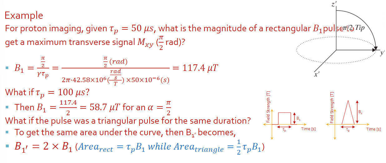
Flip angle/tip angle
The flip angle depends on the (1) shape of the RF pulse, (2) field strength B1 and (3) duration of the RF pulse 𝜏p (tau p)
For a rectangular pulse after 𝜏 seconds, the vector M has rotated at an angle α
α = 𝛾 * *B1 ** 𝜏
For any B1(t)
α (always in radians) is the integration from 0 to 𝜏 over B1(t) with respect to t (in seconds)
For the max transverse component Mxy, α is set to pi/2 radians
α = 𝛾 * *B1 ** 𝜏 = pi/2
Relaxation: The process by which M returns to steady state configuration after a B1 is done being applied
The longitudinal Mz and transverse Mxy components vary as time changes, and are descibed by Bloch Equations
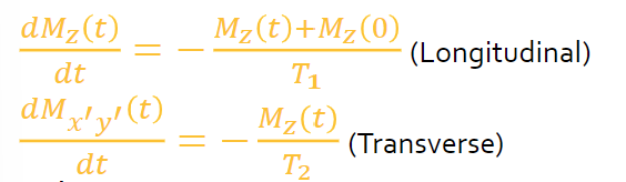
Where T1 is the longitudinal relaxation time (spin minus lattice relaxation)
T2 is the transvese relaxation time (spin minus spin relaxation)
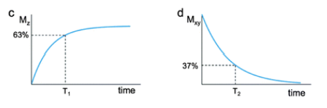
The solutions become
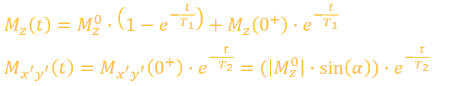
Mz^0 is the steady state of Mz
Mz(0+) is transverse magnetization Mx’y’ immediately after the RF pulse
We always measure the x-y plane and do everything else after
T1 is usually a LOT larger that T2
The longitudinal time is usually a lot longer than the transverse time (around 10 times more)
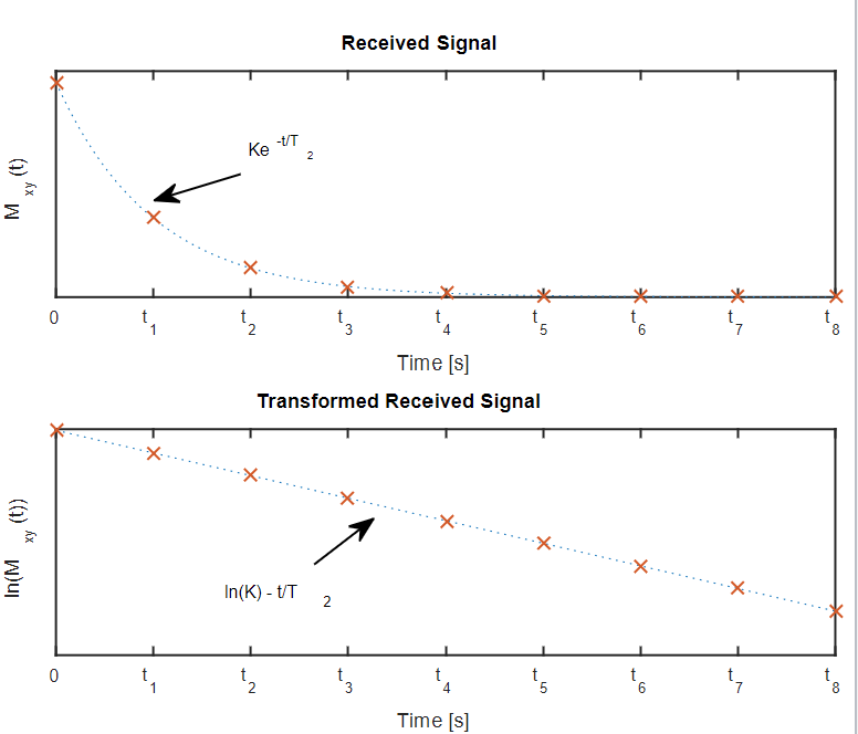
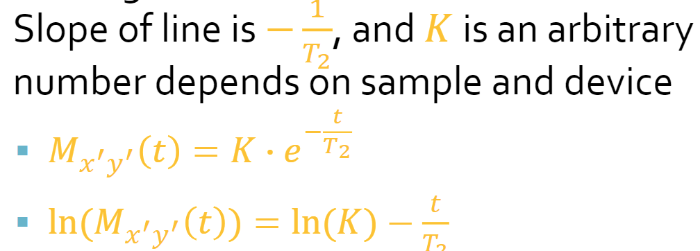
Mx’y’ decays at a faster rate (T2* instead of T2) because of signal desync
Spin Echo
To correct for dephasing and loss of Mx’y’ signal, another RF pulse (180 degree pulse) is applied to re-phase the spins
Spin echo makes the slower spins catch up with faster oens to sync the signal
Relaxation times T1 and T2 are dependant on materials (very high for water, really low for muscle, fat, tendons)
Acquisition & Contrast
Contrast in MRI is the difference between signal intensities generated by different tissues (B0, which is constant, vs gamma, which is material specific)
The difference in signal intensity is used to discriminate different tissues by representing them as brightness
Pulse sequence: Carefully timed set of scanner operations used to generate images.
Gradient-echo based pulse sequences are
Spin-echo based pulse sequences
90 degree pulse
180 degree pulse
Wait for relaxation echo
Record relaxation echo
Repeat
MR Signal Intensity
MR signal is always recorded in the xy plane
Signal intensity S of a SE sequence is
S = K x [H] x (1 - exp(-1 x TR / T1) x exp(-1 x TE/T2)
K is the scaling factor
[H] is the proton/spin density
Twice the number of spins means you have twice as large a signal
TR is the repetition time
TE is the echo time
T1 is the longitudinal relaxation time
T2 is the transverse relaxation time
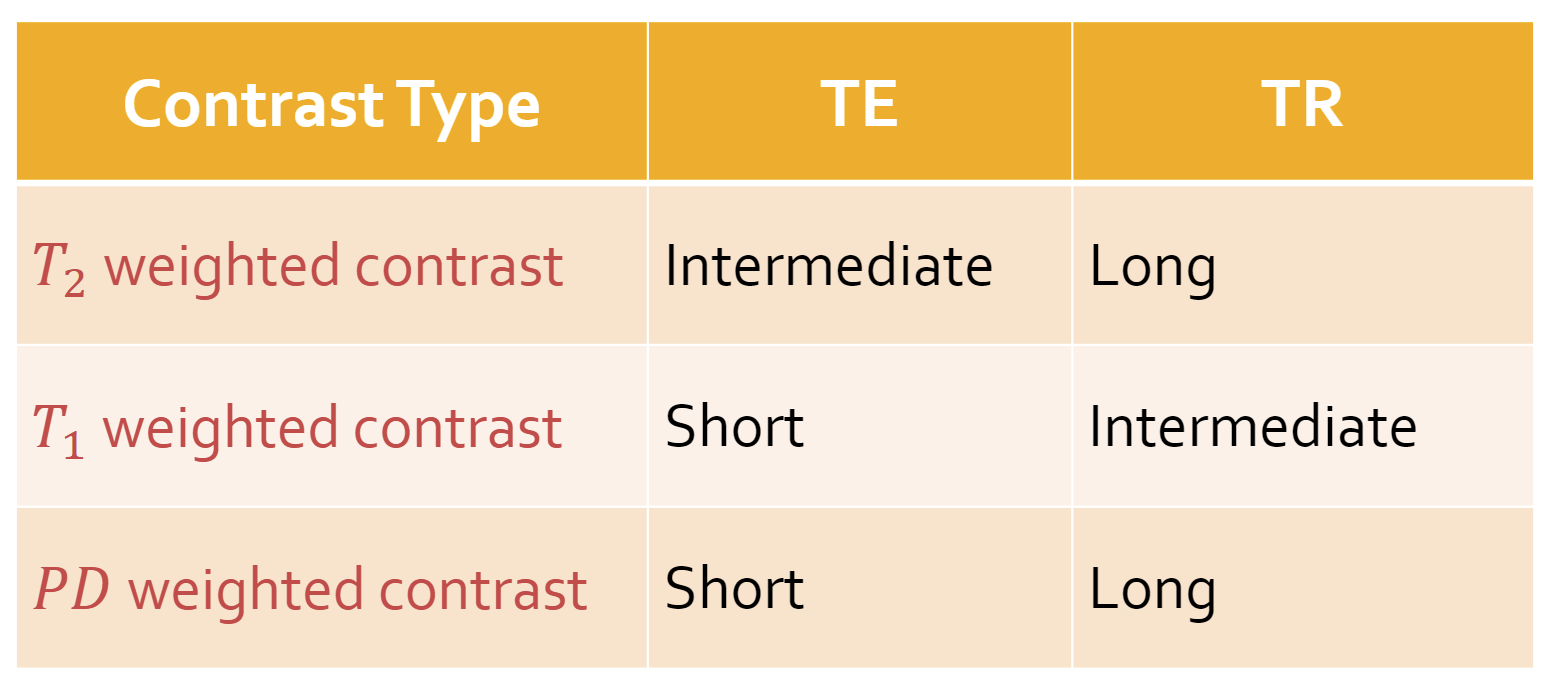
Weighting
Proton density weighting: We want a long TR and a short TE
T1 weighting: We want an intermediate TR and a short TE (becomes a constant scaling factor, less noise)
T2 weighting: We want ta long TR (minimize T1 differences) and an intermediate TE
Gradients
Adding a small gradient field (extra magnetic field) allows the same material to be differentiated if it is at different distances
Gradient affects Larmor frequency
Gradients added using more coils
Gradients are localized in x, y, and z directions
Gz is a slice selection
z-directional coils are called Maxwell pairs
Gx is frequency encoding
x-directional coils are called Golay coils
Gy is phase encoding
y-directional coils are called Golay-type coils
Gradients vary the magnetic field strength along the z-direction, which affects the frequency and phase of the spins
Fourier Transform is used to break a signal into its freuqency components (sum of sinusoids) based on their amplitude and phase
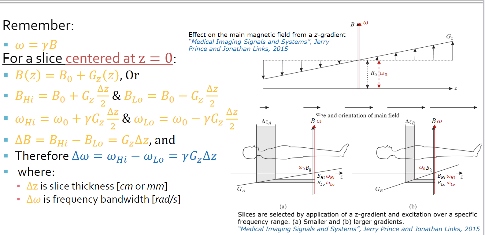
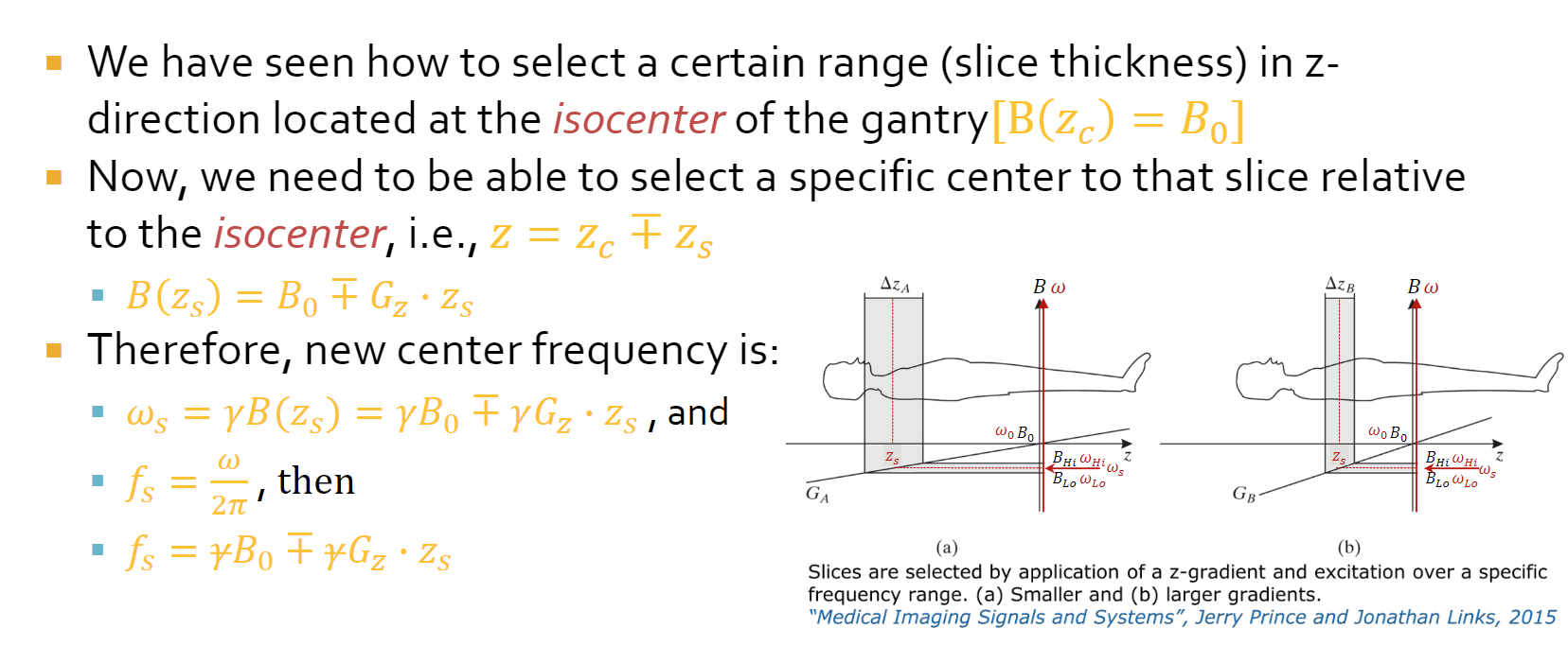
Slice thickness
Centered at z=0 , B(z) = B0 + Gz(z)
Gz is gradient strength
Overview
The magnet is used to create polarization (creates the bulk of the magnetic field)
The RF oil is used to promote excitation (sends RF energy at resonance conditions)
The gradients are used to generate spatial localization (used to form the images)
The receiver RF coils are there to target specific organs