Electromagnetic Induction
1. Electromagnetic Induction
-Motional EMF:
Concept:
When a conductor moves through a magnetic field, it induces an electromotive force (EMF).
Physics:
Free electrons in the conductor experience a force due to the magnetic field, leading to a separation of charges and an electric field within the conductor.
Formula:
The induced EMF (ε) is given by ε=BvL, where
B is the magnetic field strength,
v is the velocity of the conductor, and
L is the length of the conductor perpendicular to the direction of motion.
Equilibrium:
The induced EMF continues until the electric force from the built-up charge balances the magnetic force, eε=evB.
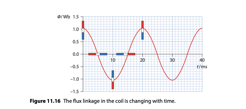
-Magnetic Flux and Faraday’s Law
Magnetic Flux (Φ): Quantified as representing the total magnetic field moving through an area A at angle
Faraday’s Law: The induced EMF in a circuit is equal to the negative rate of change of magnetic flux through the circuit
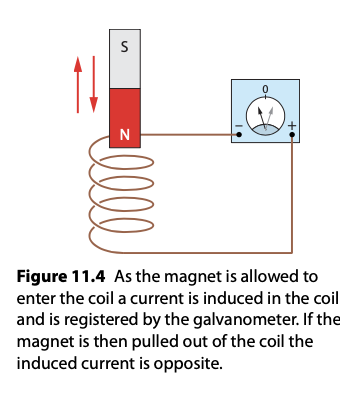
-Lenz’s Law:
The direction of the induced EMF and current is such that it opposes the change in magnetic flux that produced it, conserving energy.
Demonstrated by considering the direction of force on electrons due to the magnetic field and the resulting direction of current flow.

Applications and Implications
Lenz’s and Faraday’s laws are foundational for the functioning of electrical generators, transformers, and induction-based technologies.
The laws also provide a deeper understanding of the interplay between electricity and magnetism, showcasing the principle that changing magnetic fields can induce electrical currents.
-Transmission of Power
Alternating Current (AC)
AC is produced by an AC generator, where a coil rotating in a magnetic field induces an EMF due to electromagnetic induction.
AC changes direction periodically, with the EMF and current represented as sinusoidal functions over time.
The AC Generator
Converts mechanical energy into electrical energy using electromagnetic induction.
A coil rotates within a magnetic field, cutting through magnetic field lines, thus inducing an EMF and current.
The EMF (ε) Induced in the coil is proportional to the rate of change of magnetic flux, given by
ε=N(dΦ/dt)
N is the number of turns in the coil.
-Root Mean Square (RMS) Quantities
RMS values provide a measure of the equivalent steady DC values that would produce the same power.
peak voltage and current respectively, divided by root 2, gives the respective rms values.
RMS values are used because power in an AC circuit depends on these average values rather than the peak values.
The Transformer:
A device that changes the voltage level of AC without changing its frequency through electromagnetic induction.
Consists of primary and secondary coils around a core, with the voltage change ratio determined by the ratio of turns in the coils
Power loss in transformers occurs mainly due to eddy currents, which are minimized by laminating the core, and magnetic hysteresis.
Transformers and Power Transmission:
Step-up transformers increase voltage, reducing current for efficient long-distance power transmission, minimising power loss (P=I2R)
Step-down transformers reduce voltage to safe levels for domestic and industrial use.
Power plants use high voltages to transmit power over long distances to reduce energy loss.
Diode Bridges and Rectification
Diode bridges convert AC to direct current (DC).
Half-wave rectification uses a single diode to allow current in only one direction, resulting in a loss of half the waveform.
Full-wave rectification uses a bridge rectifier to use both halves of the AC waveform, improving efficiency.
During one half-cycle, two diodes conduct, allowing current flow in one direction; during the opposite half-cycle, the other two diodes conduct, maintaining the direction of current flow.
2. Capacitance
Definition and Basic Concept:
Capacitance (C): The ability of a system to store charge per unit voltage, defined as C, where
q is the charge
V is the potential difference
Unit of capacitance is the farad (F), where 1 F = 1 C/V.
Capacitance of a Parallel Plate Capacitor

Depends on the geometry: where
d is the distance between plates
is the permittivity of the medium
A is the plate area.
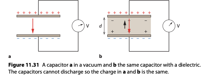
Effect of Dielectric on Capacitance
Inserting a dielectric material between the plates of a capacitor increases its capacitance by reducing the electric field, which allows the capacitor to store more charge for the same voltage.
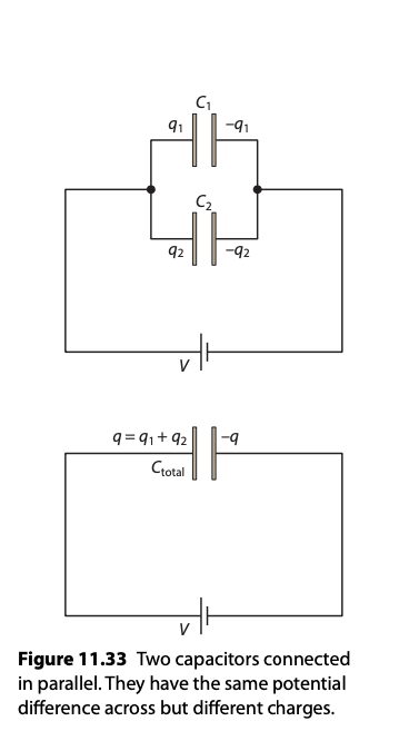
Capacitors in Parallel and Series
Parallel Configuration:
Capacitances add up ( Ctotal = C1+C2+C3…….)
Series Configuration:
Inverses of capacitances add up.
Energy Stored in a Capacitor

Represents the work done to charge the capacitor.
Charging and Discharging a Capacitor
Charging: When connected to a voltage source, the capacitor charges up following an exponential curve, approaching its maximum charge asymptotically.
Discharging: The stored energy in the capacitor is released when the circuit is closed, discharging exponentially to zero.
Capacitors in Rectification
Used in conjunction with diodes in power supply circuits to smooth the output from rectifiers.
During the half-cycle when the AC is in the correct direction, the capacitor charges up, and during the opposite half-cycle, it discharges, providing a more continuous DC output.