


Test 2 Flashcards
Weekly Test 2: Mechanical Properties (elastic, plastic, and ultimate tensile strength), Bonding and Crystal Packing
Lecture 1: Mechanical Properties - Elastic Deformations
Q. When I pull or push on a sample of steel, is it possible that I am actually changing its overall volume? Am I expanding or contracting its volume or it constant?
Uniaxial Tensile Test
- Common test — determines the relationship b/w load and deformation.
- Measures:
- Elastic Properties (Elastic Modules)
- Plastic Properties (Yield Stress)
- Failure Properties (Ultimate Tesnsile Stress)
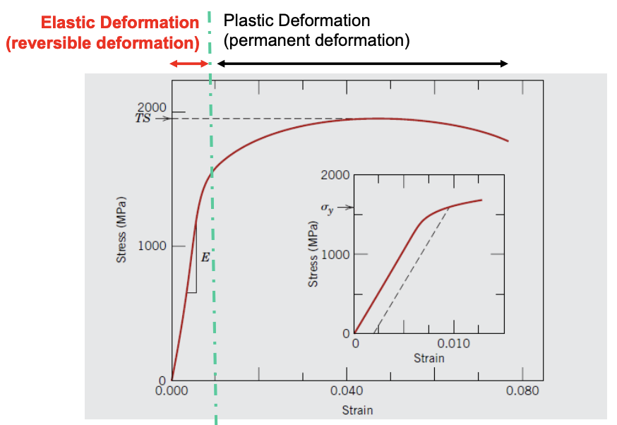
Typical Stress-Strain Curve
- Elastic is the linear region (similar to spring!)
- Steeper slope = stiffer spring/material
- Slope - modulus of elasticity
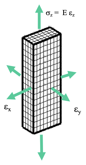
Dimensional Change Under Elastic Deformation
- When materials are stretched, the areas of it changes.
- Volume is rarely constant under elastic deformation. Most materials will expand slightly and then return back after the stress is removed.
- Poisson Ration: (ratio of the lateral and axial strains under an applied stress)
Measuring Young’s Modulus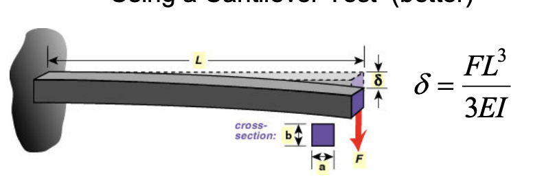
- Tensile Test: An extremely large force is used for an extremely small extension. Usually will not give an accurate reading because of the room for error. Use entensometers for accuracy!
- Cantilever Test (Better)
- X-Section for moment of inertia is
- Use equation:
Lecture 2: Mechanical Properties - Plastic Deformation
Q. Why does the stress strain curve stometimes start to go down? Is the material actually getting weaker as it deforms?
Definition
Elastic Limit: Point at which permanent deformation begins.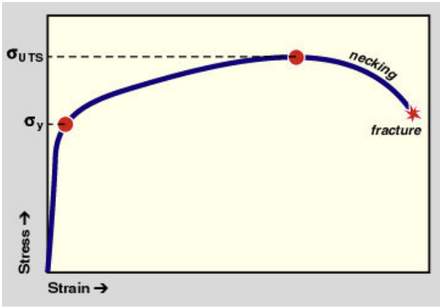
Plastic Deformation: Permanent (irreversible deformation).
Yield Stress: Maximum stress before beginning plastic deformation.
- Work Hardening: The increase in stress to continue deformation beyond the elastic limit.
- Ultimate Tensile Stress: Maximum stress value a material can support.
- Failure or Fracture Stress: Stress value at the time of failure.
- Offset Yield Stress: Technique for defining the yield stress (used in homogenous materials) - see lab about this!
Ductility
The amount of deformation a material will tolerate before failure.
It can be expressed as percent elongation or and percent reduction - related but not same value.
*QUESTION: What is the relationship between percent elongation and percent reduction?
Necking
- Localized deformation in a small section in gauge length.
- Deformation is initially distributed through the sample and eventually leading to higher localized stresses due to decrease in material — leading to a localized area of higher stresses and then necking.
- Begins at Ultimate Tensile Strength. After this point, the sample deforms primarily at the region of necking.
- High stress in necking region - same tensile force but less area.
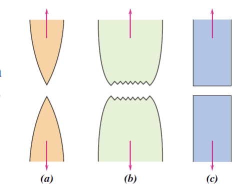
- a. Highly ductile fracture b.Moderately ductile fracture c. brittle fracture (no necking)
Proportionality of Deformation 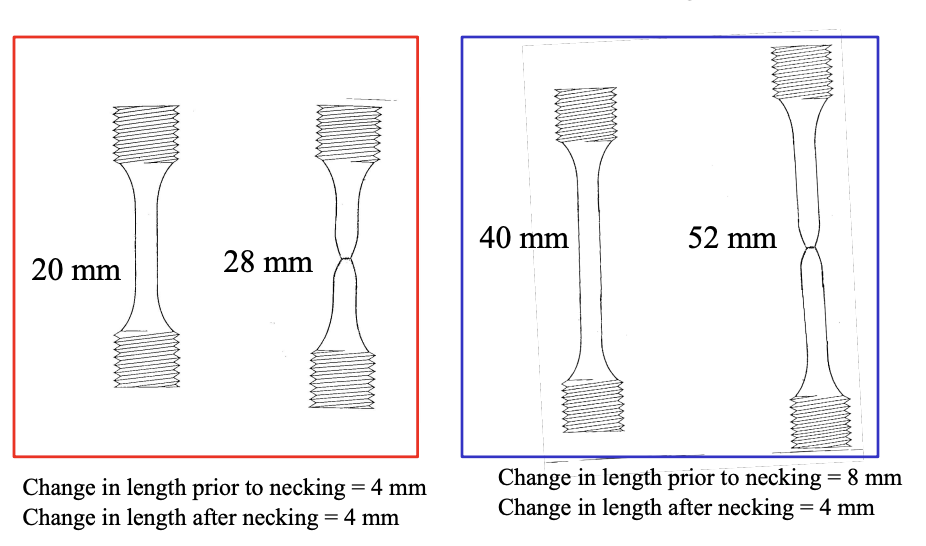
- Deformation before necking is linearly proportional as it varies with gauge length.
- Deformation ater necking is no longer proportional and will be somewhat the same as the previous length.
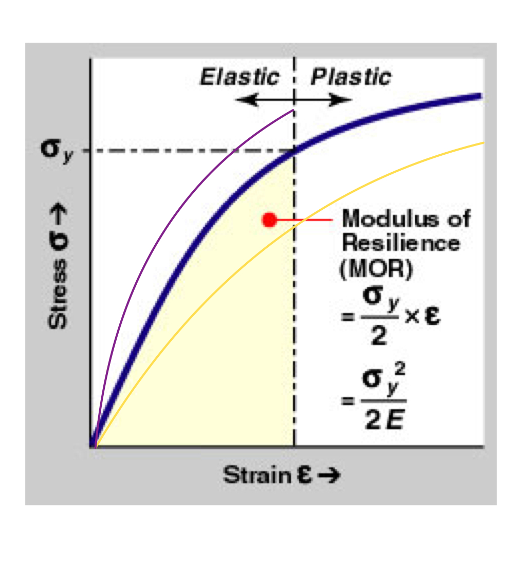
Modulus of Resilience (MOR, Ur)
Measure of elastic energy storage.
Formula:
- Area up to the elastic deformation point.
- To increase stored energy - increase the yield stress or decrease the elastic modulus as long as the other value is constant.
Toughness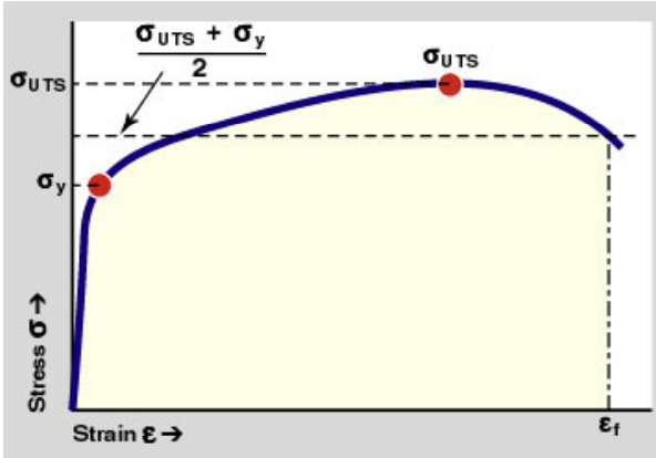
Measure of energy absorbed before failure.
Formula:
- Total area under the stress and strain curve.
- Toughness increases if increase the yield, UT stress or strain of failure.
Elastic Recovery after Plastic Deformation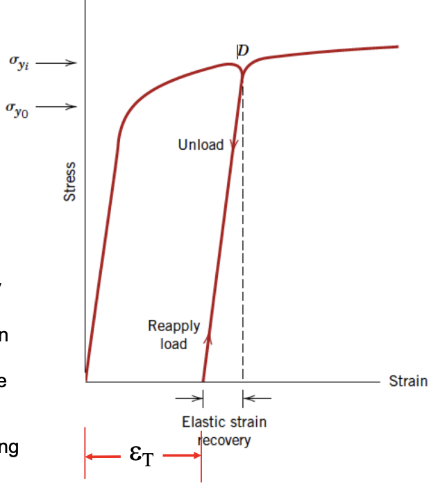
- Elastic deformation continues to accumulate after plastic deformation.
- When undergoing elastic recovery - stays deformed at new plastic deformation (strain t). When load is reapplied, the curve follows the unload curve again can be elastically deformed.
- ADD MORE WHEN DONE TUTORIAL
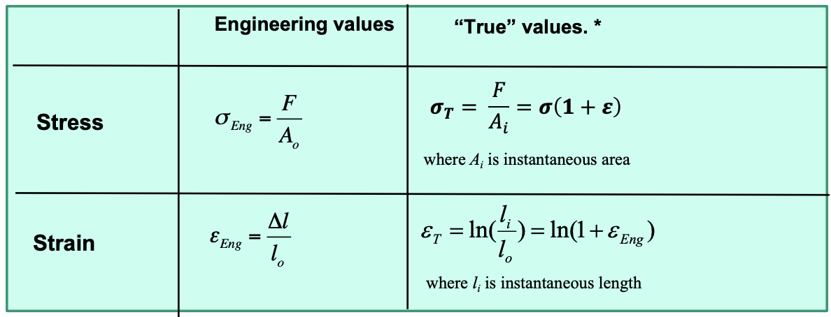
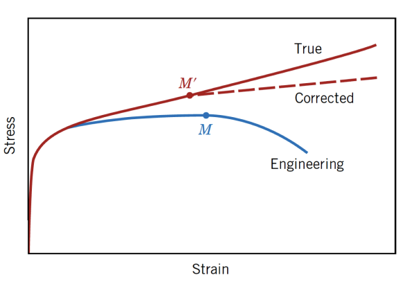
True Stress and Strain
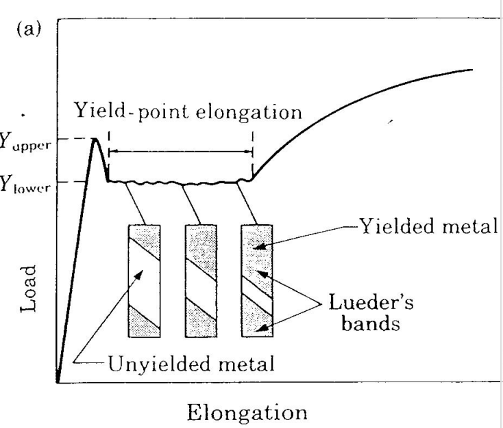
Heterogeneous Yielding in Steel
- Yielding (plastic deformation) does not accur uniformly over the length of the specimen.
- Yieleding is highly localized - deformation bands spread through the specimen competing between atom sizes.
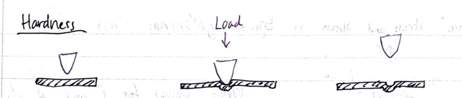
Hardness
- Measures material’s rsistacne to localized plastic deformations (dents/scratches)
- Affected by multiple mechanical properties (stiffness, yield strength, plastic characteristics)
Relationship b/w Hardness and Tensile
- Both values are proportional to each other
- Easier to conduct hardness test and then approximate the tensile strength
Lecture 3: Interatomic Bonds
Q. What materials typically have a greater linear thermal expansion coefficients, ones with high melting points or ones with low melting points ()?
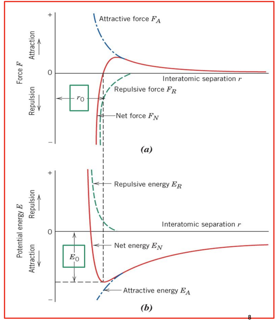
A. Conceptual Bond Diagrams
- Attractive force FA (blue) is electrostatic attraction.
- Repulsive force FR(green) is the interference of electron clouds outside of the atom.
- Net force (red) can be attractive or repulse and will be 0 at the most stable diameter.
- Bottom Graph: Potential Energy Graph - emergy required bring ions together from infinite distance apart to distance r.
- At the minimal point or equilibrium, the optimal r is reached and this is where the attractive and repulsive forces balance out.
B. Relative Physical Parameters from Conceptual Bond Diagrams
Stiffness/Modulus of Elasticity 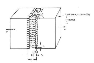
On an atomic level, when strecthing material - atoms are being stretch and then every atom returns to the same spot after load is removed.
- Value of E depends on the change of force with respect to interatomic radius (dF/dr) and total number of bonds.
- High slope results in high stiffness.
- All bonds are maintained and no atoms shift or change relative positions.
Coefficient of Thermal Expansion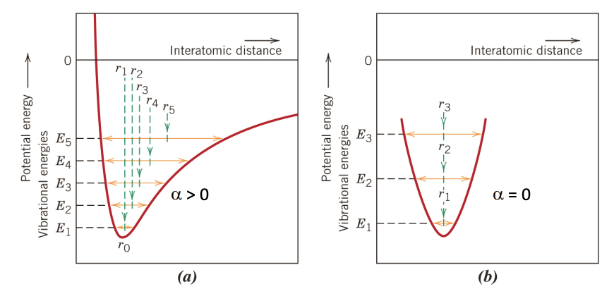
- In diagrams: E1 < E2 < E3 < E4 <E5
- Asymmetric: Meaning interatomic distance changes with the temperature. In diagram, meaning the distance is increasing with increasing temperature.
- Symmetric: means interatomic distance at the new energy level is constant with increasing temperature. For linear expansion .
Melting Temperature 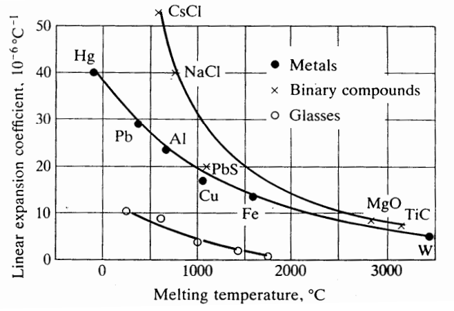
- Stronger bonds will have a lower thermal expansion coefficient and a higher-melting-point because increasing temperatures does not change bond distance as much.
- Therefore, more movement in bonds means lower-melting-point.
C. Types of Bonds
Primary Bonds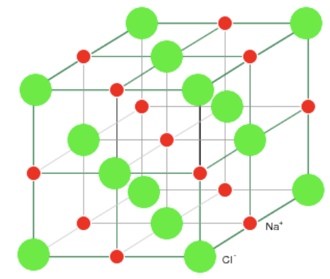
Intramolecular or chemical bonds.
Ionic Bonds
- Found both in metals and non-metals.
- Metal atoms give up their valence electron to non-metal (stolen electron)
- Metal becomes + charged and non-metal becomes - charged.
- Non-directional bonds so can form crystals.
Covalent Bonds
- In materials with a smaller difference in electronegatively.
- Sharing valence electrons (ie. orbital hybridization)
- Forms directional bonds between atoms. It will form molecules, chains, or crystal structures.
- Covalent Molecules: have shared electrons between different atoms (independent molecule units)
- Low melting and boiling points.
- Weak Van der Waal forces bewtween covalent molecular structures,
- Soft and Flexible.
- Covalent Networks: structures with continuous covalent bonds between atoms in a repeating pattern.
- High melting and boiling points.
- Only covalent bonds in a network structure.
- Very hard.
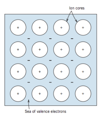
Metallic Bonds
- Found in metals and their alloys. Arranged in highly ordered crystal structures.
- Metals give up ther 1, 2, and 3 valence electron to a “sea of shared electrons”.
- Non localized electrons and non directional bonds.
- High electrical conductivity.
- Ductily of most metals
Secondary Bonds 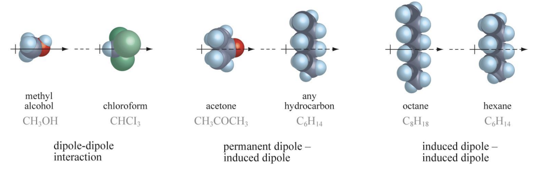
Intermolecular or physical bonds.
Van der Waals Bonds
- Dipoles from compounds causing attraction.
- London dispersion (permenent) is the weakest.
- Dipole-dipole (temporary) in polar molecules.
Hydrogen Bonds
- Strongest intermolecular bond.
- Hydrogen is bonded with lone electron from another atom with (F, O, N)
Lecture 4: Crystal Structures, Directions and Planes
Definitions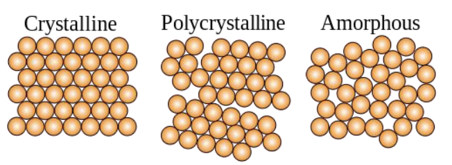
Crystal or Crystalline Solid: solid material arranged in highly ordered microscopic structure, forming a crystal lattice in all directions.
Polycrystalline Solid: solid composed of many grains in crystal structure.
Amorphous Solids: solid that is not organized into any definite lattice pattern.
Crystal Morphology: refers to the shape and size of crystals.
Microstructure: refers to he structure features of an alloy (grain or phase structure)
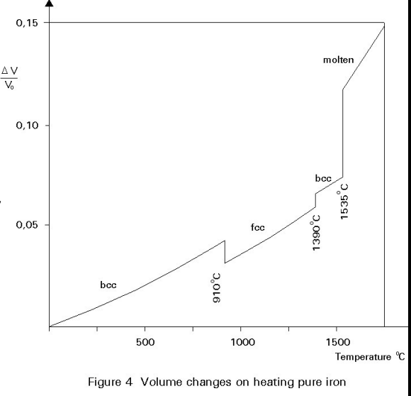
Structure and Mechanical Properties
Each phase (same material), BCC and FCC, has a different crystal structures.
- The graph shows the volume changes and crystals form as iron is heated.
- Each different phase (crystal structure) may also have different mechanical, thermal, and electrical properties.
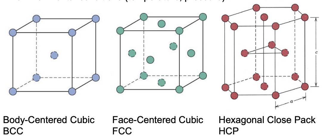
Three Common Crystal Structures for Metals
Different crystals form due to different types of bonds, sometimes crystal structure will change due to environment (temeperature, pressure)
Definitions
Unit Cell: minimum volumetric unit which repeats. Has a # of atoms per cell and length wrt atomic radius.
Coordination Number: # of atoms which are in constant with a one particular atom.
Atomic Packing Factor: fraction of unit cell value which is occupied by the hard-sphere atoms.
- APF = (volume of atoms in cell)/(unit cell volume)
Summary of Crystals
Structure | Atoms/Unit Cell | Coordination # | APF | Lattice Parameter (a) |
|---|---|---|---|---|
BCC | 2 | 8 | 0.68 | R |
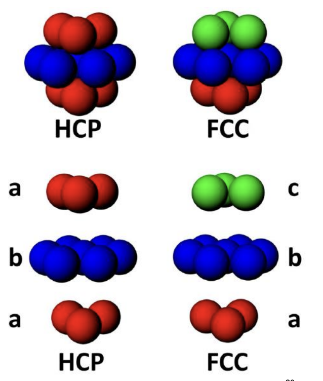
FCC (ABABAB) | 4 | 12 | 0.74 | R |
HCP (ABCABC) | 6 | 12 | 0.74 | 2R |
Density Calculation
= number of atoms per unit cell
= atomic weight g/mol
= unit cell volume =
= Avogardro’s Number = atoms/mol
Crystal Directions and Planes
At scale of a single crystal, following mechanical properties depend on orientation wrt crystallographic planes.
- Brittle fractures can occur on specific planes.
- Elastic properties of crystals depend on direction of loading.
- Permanent deformation occurs by sliding b/w crystal planes.
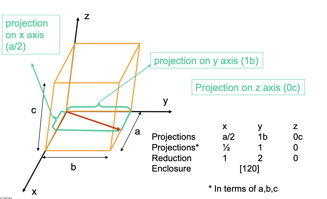
Defining Directions
- Vector: passes through the origin of the coordinate system.
- Length of Vector: is determined by length of unit cell dimensions a, b, and c.
- Expressed as [u v w] such that u = x, v = y, w = z.
- Negative gets bar on top
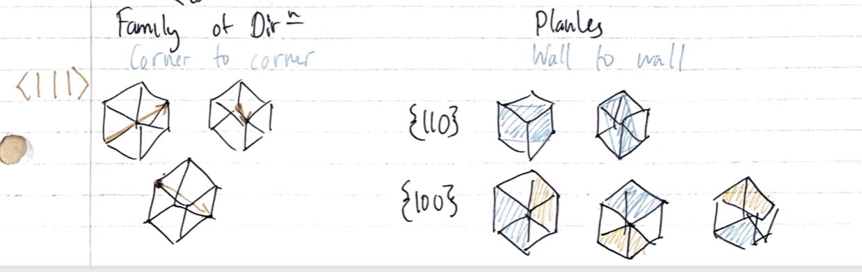
Directionality
Anisotropic: Having different properties in different directions - usually in materials with smaller grains.
Isotropic: Properties are independent of direction.
Crystallographic Planes (Miller Indices)
Crystallographic Planes are specified by 3 Miller Indices as [h k l], representing the normal vector to the plane.
Defining Planes
- If plane passes through the selected origin pick a new origin to be established.
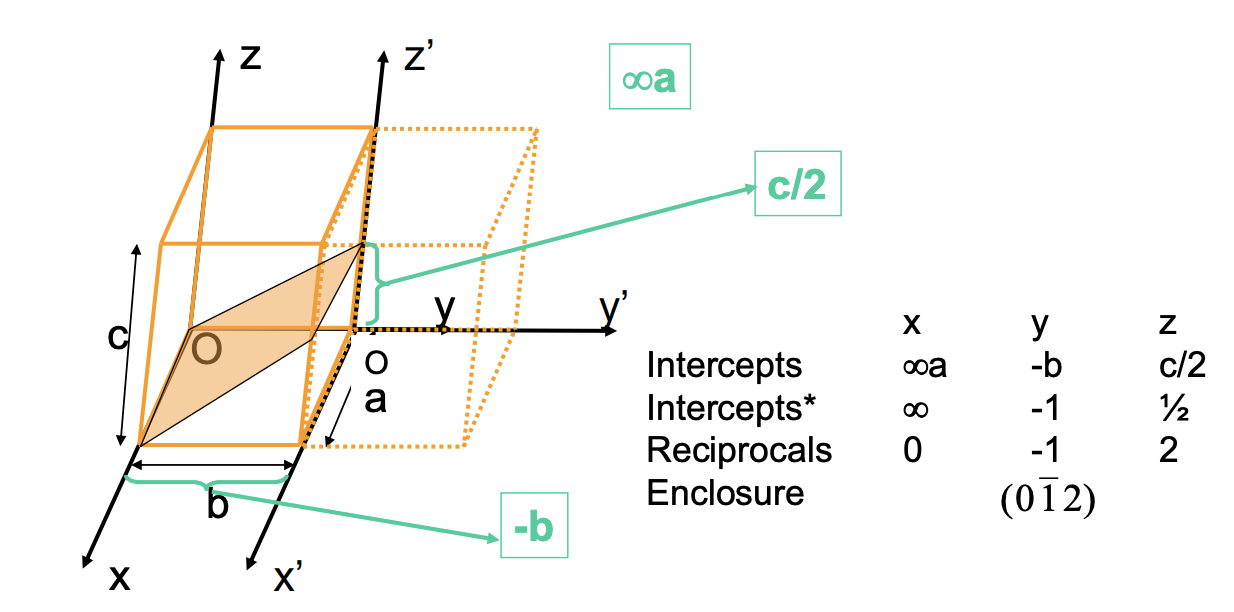
- Determine the length of the plane finding where it intersects on x, y, and z.
- Take the reciprocals of these numbers. A plane that parallels an axis may be considered an infinite intercept and thus, a zero reciprocal.
- Change numbers to the smallest integers (get rid of the fractions).
- Then specify them within the parentheses such that (h k l) - negative gets bar on top
Lecture 5: Polycrystalline Strucutres and Disolcations
Q. Why are some pure metals inherently more ductile than others? What is it about their crystal structure which might be different?
Types of Imperfections in Crystal Structures
Anything that disrupts the orderly pattern of unit cells in a crystal structure can be considered imperfect.
0. Point Defects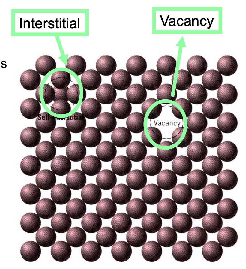
- Self Interstitial Atoms (extra atom)
- Squeezed into voids which are not normally occupied — can generate high stresses in the material.
- Does not happen commonly.
- Vacancies (atom is missing)
- N = # of atoms per unit volume.
- Qv = activation energy for vacancy formation.
- T = temperature.
- R = 8.31 J/K*mol
- As T increases, Nv increases.
- Most common.
- Vacancies allow atoms to move in the solid through a process of diffusion.
- Recrystallization, grain growth, phase transformations, creep.
- Rearrange atoms to get to lower energy configuration.
- Impurity Atoms (replacement atom)
- Solid Solutions are mixtures of 2 different types of atoms - solubility limit is the maximum amount of an element that can dissolve in another element.
- Substitutional: alloy atoms replace host atoms in the crystal structure (must be of similar size)
- Interstitial: small alloy atoms fit into spaces between host atoms (must be smaller atoms)
1. Line defects, aka Dislocations
- Edge Dislocation
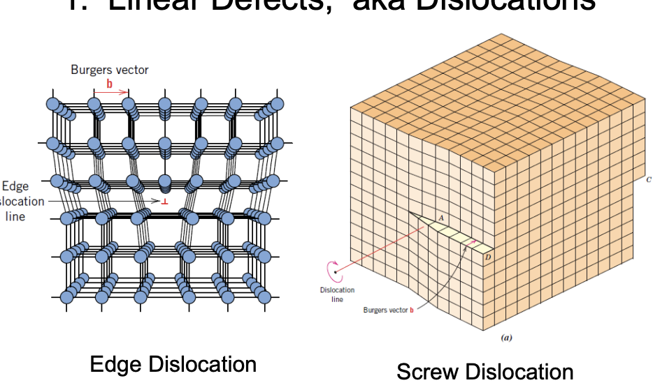
- The presence of an extra half of the plane in the crystal structure.
- Can form when materials are deformed.
- Explains why yield stresses are lower compared to expected values.
- Screw Dislocation
- Bulk sample goes through partial shear.
- Shifted by 1 or more unit cells and two edges need to accommodate.
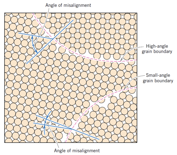
2. Planar interfaces
- Grain Boundaries
- These regions of atomic disorder and higher energy are more chemically active.
- The angle of misalignment can be found by finding the angle between the two high-density lines near the grain boundary.
Weekly Test 5: Strengthening Mechanisms, Failure (Fracture, Fatigue and Creep
Weekly Test 7: Phase Diagrams, Steel, Applications and Manufacturing Processes