Physics
AP Physics C: Electricity and Magnetism
Electric-Charge
Coulomb's-Law
Electric-Charge
Conservation-of-Charge
Conductors
Insulators
Law-of-Electrostatics
Electric-Potential-Difference
Electric-Potential-Difference
Charging-and-Discharging
Gauss'-Law
Electric-Field-Strength
Electromagnetism
Magnetic-Flux
Magnetic-Flux
Maxwell’s-Equations
Faraday's-Law
Lenz's-Law
Ampère's-Law
Biot-Savart-Law
Right-Hand-Rule
Right-Hand-Rule
Resistance
Ohm's Law
Circuits
Capacitors
Kirchhoff's-Voltage-Law
Kirchhoff's-Current-Law
Electric-Shielding
Capacitance
Parallel-Plate-Capacitor
12th


AP Physics C: Electricity and Magnetism Ultimate Guide
Unit 1: Electrostatics
1.1: Electric Charge & Coulomb's Law
Charge
Charge: It is a fundamental property of matter that describes the amount of electrical energy present in an object.
It is a scalar quantity that can be either positive or negative.
The SI unit of charge is Coulomb (C).
Charge | Coulombs | Elementary Charge |
|---|---|---|
+1 | 1.602 × 10^-19 C | 1 e |
+2 | 3.204 × 10^-19 C | 2 e |
+3 | 4.806 × 10^-19 C | 3 e |
-1 | -1.602 × 10^-19 C | -1 e |
-2 | -3.204 × 10^-19 C | -2 e |
-3 | -4.806 × 10^-19 C | -3 e |
Electric Charge
Electric charge: It is a fundamental property of matter that arises from the presence or absence of electrons in an atom.
It can be positive or negative, and like charges repel while opposite charges attract.
The unit of electric charge is the Coulomb (C), and the basic unit of charge is the electron, which has a charge of
-1.602 x 10^-19 C.Electric charge plays a crucial role in many areas of physics, including electromagnetism and electrostatics. It is also the basis for the study of electric circuits and electronics.
Conservation of Charge
The law of conservation of charge is a fundamental principle of physics and is applicable to all physical systems.
It is closely related to the conservation of energy and momentum.
The principle of conservation of charge is used in various fields of science, including electrostatics, electrodynamics, and quantum mechanics.
The conservation of charge is a consequence of the symmetry of physical laws under the transformation of time.
It is a fundamental principle of nature and has been experimentally verified to a high degree of accuracy.
It is an important concept in the study of electricity and magnetism and is used to explain many phenomena, including the behavior of electric circuits and the interaction of charged particles with electromagnetic fields.
It is a fundamental principle that underlies many of the technological advances of the modern world, including electronics, telecommunications, and power generation.
Conductors and Insulators
Conductors: These are materials that allow electric charge to flow freely through them.
Insulators: These are materials that do not allow electric charge to flow easily.
Metals are good conductors, while materials such as rubber and plastic are good insulators.
Law of Electrostatics
The law of electrostatics is a set of fundamental principles that govern the behavior of electric charges at rest.
These laws are based on observations and experiments conducted by scientists over the years.
Coulomb's Law
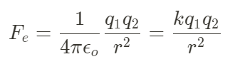
Coulomb's law: This law states that the force between two point charges is directly proportional to the product of their charges and inversely proportional to the square of the distance between them. Mathematically, it can be expressed as:
F = k * (q1 * q2) / r^2where:
F is the force between the charges
q1 and q2 are the magnitudes of the charges
r is the distance between them
k is the Coulomb constant.
Electric Field
Electric field: A region in space where an electric charge experiences a force.
The strength of the electric field at a point is defined as the force per unit charge acting on a test charge placed at that point. Mathematically, it can be expressed as:
E = F / qwhere:
E is the electric field strength
F is the force acting on the test charge
q is the magnitude of the test charge.
Electric Potential
Electric potential: It is the amount of work required to move a unit charge from one point to another in an electric field. It is measured in volts (V) and is defined as:
V = W / qwhere:
V is the electric potential
W is the work done in moving the charge
q is the magnitude of the charge.
Electric Potential Difference
Electric potential difference is the difference in electric potential between two points in an electric field. It is measured in volts (V) and is defined as:
ΔV = V2 - V1where:
ΔV is the electric potential difference
V1 is the electric potential at point 1
V2 is the electric potential at point 2.
Charging and Discharging
Charging
Charging: It is the process of adding electrical energy to a system.
In the case of a battery, charging involves applying an external voltage to the battery terminals, which causes a chemical reaction that stores energy in the battery.
The charging process is typically slower than discharging, as it involves a chemical reaction that takes time to complete.
Overcharging a battery can cause damage or even lead to a fire or explosion, so it's important to use a charger that is designed for the specific type of battery being charged.
Discharging
Discharging: It is the process of releasing electrical energy from a system.
In the case of a battery, discharging involves allowing the stored energy to flow out of the battery and into a load, such as a light bulb or motor.
The rate of discharge depends on the load connected to the battery and the capacity of the battery itself.
Discharging a battery too quickly can cause it to overheat and potentially fail, so it's important to use a load that is appropriate for the battery's capacity.
Electrostatic Force & Coulomb's Law
Electrostatic force is the force that exists between electrically charged particles. This force can be either attractive or repulsive, depending on the charges of the particles. The strength of the electrostatic force is determined by Coulomb's Law. The equation for calculating electrostatic force is:
Coulomb's Law states that the electrostatic force between two charged particles is directly proportional to the product of their charges and inversely proportional to the square of the distance between them. The mathematical expression for Coulomb's Law is:
F = k * (q1 * q2) / r^2where:
F is the electrostatic force
q1 and q2 are the charges of the particles
r is the distance between them
k is Coulomb's constant.
Coulomb's constant is a proportionality constant that depends on the medium between the charged particles.
In a vacuum, Coulomb's constant has a value of approximately
9 x 10^9 N*m^2/C^2.The electrostatic force between two charged particles can be attractive or repulsive, depending on the signs of their charges.
Like charges (positive and positive, or negative and negative) repel each other, while opposite charges (positive and negative) attract each other.
1.2: Electric Fields & Electric Potential
Electric Fields
An electric field is a vector field that describes the force exerted on a charged particle by other charged particles.
The electric field is defined as the force per unit charge that a test charge would experience if placed in the field.
Rules for Drawing Electric Fields
Electric field lines always start on positive charges and end on negative charges.
The number of electric field lines leaving a positive charge or entering a negative charge is proportional to the magnitude of the charge.
Electric field lines never cross each other.
Electric field lines are always perpendicular to the surface of a conductor.
The density of electric field lines is proportional to the strength of the electric field.
Electric Field Strength
Electric field strength is the force per unit charge experienced by a test charge placed in an electric field. It is a vector quantity and is denoted by E.
The electric field strength at a point in an electric field is given by the formula:

where:
E is the electric field strength
F is the force experienced by the test charge
q is the magnitude of the test charge.
The SI unit of electric field strength is newtons per coulomb (N/C).
The direction of the electric field strength is the direction of the force experienced by a positive test charge placed in the electric field.
Electric Field Strength due to a Point Charge
The electric field strength due to a point charge is given by Coulomb's law:
E = k * Q / r^2where:
E is the electric field strength
k is Coulomb's constant
Q is the magnitude of the point charge
r is the distance between the point charge and the test charge.
Electric Field Strength due to a Uniformly Charged Sphere
The electric field strength due to a uniformly charged sphere at a point outside the sphere is given by:
E = k * Q / r^2where:
E is the electric field strength
k is Coulomb's constant
Q is the total charge on the sphere
r is the distance between the center of the sphere and the test charge.
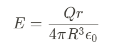
Inside the sphere, the electric field strength is given by:
E = k * Q * r / R^3where:
R is the radius of the sphere
r is the distance between the center of the sphere and the test charge.
Electric Fields in Conductors
In a conductor, electric charges are free to move.
When an electric field is applied to a conductor, the charges will move until they reach a state of equilibrium.
The electric field inside a conductor is zero, as the charges will continue to move until the electric field is cancelled out.
Any excess charge on a conductor will reside on its surface, as the charges repel each other and move as far away from each other as possible.
The electric field just outside the surface of a conductor is perpendicular to the surface and proportional to the surface charge density.
Electric Fields in Insulators
In an insulator, electric charges are not free to move.
When an electric field is applied to an insulator, the charges will not move, but the atoms and molecules will become polarized.
The electric field inside an insulator is not zero, as the charges are not free to move and will experience a force.
The electric field just outside the surface of an insulator is perpendicular to the surface and proportional to the surface charge density, similar to a conductor.
1.3: Point Charges - Fields & Potentials
Work Done by Electric Fields
Electric fields can do work on charged particles.
Work is done when a force moves an object over a distance.
The work done by an electric field on a charged particle is given by the equation W = qEd, where W is the work done, q is the charge of the particle, E is the strength of the electric field, and d is the distance the particle is moved.
Applications of Electric Fields & Work
Electric fields and work are used in many applications, such as:
Capacitors: devices that store electric charge and energy.
Electric motors: devices that convert electrical energy into mechanical energy.
Particle accelerators: devices that use electric fields to accelerate charged particles to high speeds.
Electrostatic precipitators: devices that use electric fields to remove pollutants from the air.
Electric Potential Energy
Electric potential energy: It is the energy that a charged particle possesses due to its position in an electric field. It is defined as the amount of work required to move a charged particle from infinity to a point in the electric field.
The SI unit of electric potential energy is joule (J).
where ∆Ue is the change in Electric Potential Energy.
Potential Difference
Potential difference: It is the difference in electric potential energy per unit charge between two points in an electric circuit.
It is also known as voltage and is measured in volts (V).
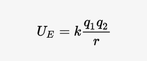
Electric Potential of a Point Charge
The electric potential at a point in space is the amount of work required to bring a unit positive charge from infinity to that point.
The electric potential of a point charge is given by:
V = kq/rwhere:
V is the electric potential
k is Coulomb's constant
q is the charge of the point charge
r is the distance between the point charge and the point where the electric potential is being calculated.
Some key points to note about the electric potential of a point charge are:
The electric potential at infinity is zero.
The electric potential is a scalar quantity and is measured in volts (V).
The electric potential is a function of distance from the point charge and decreases as the distance increases.
The electric potential is positive for a positive point charge and negative for a negative point charge.
The electric potential can be used to calculate the electric field at any point in space. The electric field is given by:
E = -∇Vwhere:
E is the electric field
∇ is the gradient operator.
The negative sign indicates that the electric field points in the direction of decreasing electric potential.
1.4: Gauss' Law
Gauss' Law is a fundamental principle in electromagnetism that relates the electric flux through a closed surface to the charge enclosed within that surface. It is named after the German mathematician and physicist Carl Friedrich Gauss.
The statement of Gauss' Law is as follows:
The electric flux through any closed surface is proportional to the charge enclosed within that surface.
In mathematical terms, this can be expressed as:
∮E⋅dA = Q/ε0where:
∮E⋅dA is the electric flux through a closed surface
Q is the charge enclosed within that surface
ε0 is the permittivity of free space.
Gauss' Law has many important applications in electromagnetism, including:
Calculating the electric field due to a charged object or distribution of charges
Determining the charge distribution within a conductor
Analyzing the behavior of electric fields in dielectric materials
Understanding the behavior of electric fields near conductors and insulators
Flux
Flux is the amount of a physical quantity passing through a given surface.
In electrostatics, electric flux is the measure of the electric field passing through a given surface.
Mathematically, electric flux can be expressed as:
Φ = ∫E ⋅ dAwhere,
Φ is the electric flux through a surface,
E is the electric field, and
dA is the area vector of the surface.
Gauss's Law Flux Sample Problem
A point charge of +2 nC is located at the center of a sphere of radius 10 cm. Find the electric flux through the surface of the sphere.
Solution
We can use Gauss's law to solve this problem. Gauss's law states that the electric flux through a closed surface is proportional to the charge enclosed within the surface. Mathematically, it can be written as:
Φ = Q / ε₀where Φ is the electric flux, Q is the charge enclosed within the surface, and ε₀ is the permittivity of free space.
In this problem, the charge enclosed within the surface is the point charge of +2 nC. Therefore, we can write:
Q = +2 nCThe surface in this problem is a sphere of radius 10 cm. We can choose a Gaussian surface that is also a sphere of radius 10 cm. Since the point charge is located at the center of the sphere, the electric field is radial and has the same magnitude at every point on the Gaussian surface.
Using the formula for the electric field due to a point charge, we can find the magnitude of the electric field at the surface of the Gaussian sphere:
E = kQ / r²where k is Coulomb's constant, Q is the point charge, and r is the radius of the Gaussian sphere.
Substituting the given values, we get:
E = (9 × 10^9 Nm²/C²) × (2 × 10^-9 C) / (0.1 m)²E = 36 N/C
The electric flux through the Gaussian surface is then:
Φ = E × Awhere A is the area of the Gaussian surface. Since the Gaussian surface is a sphere, its area is:
A = 4πr²
Substituting the given values, we get:
A = 4π × (0.1 m)²A = 0.04π m²
Therefore, the electric flux through the surface of the sphere is:
Φ = (36 N/C) × (0.04π m²)Φ = 4.52 Nm²/C
1.5: Other Charge Distributions - Fields & Potentials
Extended Charge Distributions
Extended charge distributions: This refer to the distribution of electric charge over a three-dimensional object.
The electric field produced by an extended charge distribution can be calculated using Coulomb's law, but the calculation is more complex than for a point charge.
Continuous Charge Distributions
These charge distributions are those where the charge is distributed continuously over a volume or surface.
The charge density, which is the amount of charge per unit volume or unit area, is used to describe the distribution.
The electric field produced by a continuous charge distribution can be calculated using integration.
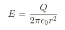
Spherical Charge Distributions
These charge distributions are those where the charge is distributed uniformly over the surface of a sphere.
The electric field produced by a spherical charge distribution can be calculated using Gauss's law, which relates the electric flux through a closed surface to the charge enclosed within the surface.
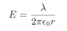
Cylindrical Charge Distributions
These charge distributions are those where the charge is distributed uniformly over the surface of a cylinder.
The electric field produced by a cylindrical charge distribution can also be calculated using Gauss's law.
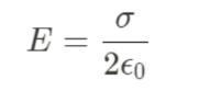
Planar Charge Distributions
These charge distributions are those where the charge is distributed uniformly over a flat surface.
The electric field produced by a planar charge distribution can be calculated using Coulomb's law, but the calculation is simplified by assuming that the surface is infinite and the charge is distributed uniformly.
Gauss' Law for Various Shapes
Line of Charge |
|
|---|---|
Point, Hoop, or Sphere |
|
Sphere |
|
Insulating Sheet of Charge |
|
Unit 2: Conductors, Capacitors, Dieletrics
2.1: Electrostatics with Conductors
Electric Field on the Surface of a Conductor
Electric field is a vector quantity that describes the force experienced by a charged particle in an electric field.
Electric field lines are perpendicular to the surface of a conductor at every point on the surface.
The electric field inside a conductor is zero, and any excess charge resides on the surface of the conductor.
The electric field on the surface of a conductor is perpendicular to the surface and is proportional to the surface charge density.
The electric field just outside the surface of a conductor is perpendicular to the surface and is equal to the electric field inside the conductor.
The electric field just inside the surface of a conductor is perpendicular to the surface and is equal to the electric field outside the conductor.
The electric field on the surface of a conductor is strongest where the surface is most curved, and weakest where the surface is most flat.
The electric field on the surface of a conductor is affected by the presence of other charges and conductors in the vicinity.
Electric Shielding
Electric shielding: It is the process of reducing the electric field in a space by surrounding it with a conductive material.
It is used to protect sensitive electronic equipment from electromagnetic interference (EMI) and radio frequency interference (RFI).
Electric shielding can be achieved by using conductive coatings, conductive fabrics, or metal enclosures.
The effectiveness of electric shielding depends on the conductivity of the material used, the thickness of the shielding, and the frequency of the electromagnetic waves.
Faraday Cages
Faraday cage: It is a type of electric shielding that completely surrounds a space with a conductive material, creating a barrier that prevents electromagnetic waves from entering or leaving the space.
These are used to protect sensitive electronic equipment from lightning strikes, electromagnetic pulses (EMPs), and other forms of electromagnetic interference.
These can be made from a variety of materials, including copper, aluminum, and steel.
The effectiveness of a Faraday cage depends on the conductivity of the material used, the thickness of the shielding, and the frequency of the electromagnetic waves.
Faraday cages are commonly used in electronic devices such as cell phones, computers, and radios to prevent interference from external sources.
2.2: Capacitors
Capacitor: An electronic component that stores electrical energy in an electric field. It consists of two conductive plates separated by a dielectric material.
Capacitance: It is the ability of a capacitor to store charge.
C = Q/Vwhere
C is capacitance
Q is charge
V is voltage.
Charging and Discharging
When a capacitor is connected to a voltage source, it charges up to the voltage of the source. The time it takes to charge depends on the capacitance and the resistance of the circuit.
When a charged capacitor is disconnected from the voltage source, it discharges through the circuit. The time it takes to discharge depends on the capacitance and the resistance of the circuit.
Parallel Plate Capacitor
Parallel plate capacitor: It is a device that stores electrical energy in an electric field between two parallel conducting plates. It consists of two parallel plates separated by a dielectric material.
The capacitance of a parallel plate capacitor is given by:
C = εA/dwhere
C is the capacitance
ε is the permittivity of the dielectric material between the plates
A is the area of each plate
d is the distance between the plates.
The electric field between the plates of a parallel plate capacitor is given by:
E = V/dwhere:
E is the electric field
V is the potential difference between the plates
d is the distance between the plates.
The energy stored in a parallel plate capacitor is given by:
U = (1/2)CV^2where:
U is the energy stored
C is the capacitance
V is the potential difference between the plates.
Types of Capacitors
Ceramic capacitors: These are the most commonly used type of capacitor.
They are made of ceramic materials and have a high dielectric constant.
They are small in size and have a low cost.
They are used in high-frequency applications, such as in filters and resonant circuits.
Electrolytic capacitors: These are polarized capacitors that use an electrolyte as the dielectric.
They have a high capacitance and are used in low-frequency applications, such as in power supplies and audio circuits.
They are available in two types: aluminum electrolytic capacitors and tantalum electrolytic capacitors.
Film capacitors: These are non-polarized capacitors that use a thin plastic film as the dielectric.
They have a high stability and are used in high-frequency applications, such as in radio and television circuits. They are available in two types: polyester film capacitors and polypropylene film capacitors.
Tantalum capacitors: These are polarized capacitors that use tantalum metal as the anode.
They have a high capacitance and are used in low-frequency applications, such as in power supplies and audio circuits.
They are smaller in size than aluminum electrolytic capacitors and have a longer lifespan.
Variable capacitors: These are capacitors whose capacitance can be adjusted.
They are used in tuning circuits, such as in radios and televisions.
They are available in two types: air variable capacitors and trimmer capacitors.
Energy in a Capacitor
The energy stored in a capacitor can be calculated using the formula:
E = 1/2 * C * V^2where:
E is the energy stored in joules
C is the capacitance of the capacitor in farads
V is the voltage across the capacitor in volts.
The energy stored in a capacitor is proportional to the square of the voltage across it.
This means that if the voltage across a capacitor is doubled, the energy stored in it will be quadrupled.
The energy stored in a capacitor can be used to do work.
For example, a capacitor can be used to power a flash in a camera.
When the flash is triggered, the energy stored in the capacitor is released, producing a bright flash of light.
The energy stored in a capacitor can also be used to filter out unwanted frequencies in a circuit.
Capacitors are often used in filters to remove noise from signals.
2.3: Dielectrics
Dielectrics: These are materials that do not conduct electricity easily.
They are used in capacitors to store electrical energy and in insulators to prevent electrical current from flowing.
Polar dielectrics have a permanent dipole moment due to the presence of polar molecules.
They align themselves in an electric field and increase the capacitance of the capacitor.
Examples of polar dielectrics include water, mica, and ceramic.
Non-polar dielectrics do not have a permanent dipole moment.
They are made up of non-polar molecules and do not align themselves in an electric field.
Examples of non-polar dielectrics include air, vacuum, and oil.
Dielectric strength: It is the maximum electric field that a dielectric material can withstand before it breaks down and conducts electricity. It is measured in volts per meter (V/m). The dielectric strength of a material depends on its thickness, temperature, and the frequency of the electric field.
Common Dielectrics
Material | Dielectric Constant (k) |
|---|---|
Air | 1.0006 |
Vacuum | 1.0 |
Teflon | 2.1 - 2.3 |
Glass | 4.5 - 8.5 |
Water | 80.4 |
Diamond | 5.5 |
Why Does Adding a Dielectric Increase the Capacitance?
Polarization of Dielectric Material
When a dielectric material is inserted between the plates of a capacitor, it gets polarized due to the electric field produced by the capacitor.
The polarization of the dielectric material creates an additional electric field that opposes the electric field produced by the capacitor.
This reduces the effective electric field between the plates of the capacitor, which in turn increases the capacitance of the capacitor.
Increase in Electric Flux Density
The electric flux density between the plates of a capacitor is directly proportional to the electric field produced by the capacitor.
When a dielectric material is inserted between the plates of a capacitor, the electric flux density increases due to the polarization of the dielectric material. This increase in electric flux density leads to an increase in the capacitance of the capacitor.
Reduction in Electric Field
The electric field between the plates of a capacitor is reduced when a dielectric material is inserted between the plates.
This is because the dielectric material reduces the potential difference between the plates of the capacitor.
As a result, the electric field between the plates of the capacitor is reduced, which in turn increases the capacitance of the capacitor.
Unit 3: Electric Circuits
3.1: Electric Circuits
Circuit Quantities
Voltage: It is the difference in electric potential between two points in a circuit. It is measured in volts (V) and is represented by the symbol "V".
It is the driving force that causes current to flow in a circuit.
Current: It is the flow of electric charge through a circuit. It is measured in amperes (A) and is represented by the symbol "I". It is the rate at which charge flows through a circuit.
Resistance: It is the opposition to the flow of electric current in a circuit. It is measured in ohms (Ω) and is represented by the symbol "R". It is determined by the material and dimensions of the conductor.
Power: It is the rate at which energy is transferred in a circuit. It is measured in watts (W) and is represented by the symbol "P". Power is calculated by multiplying voltage and current.
Frequency: It is the number of cycles per second in an alternating current (AC) circuit. It is measured in hertz (Hz) and is represented by the symbol "f". It determines the speed at which the AC signal alternates.
Impedance: It is the total opposition to the flow of electric current in a circuit. It is measured in ohms (Ω) and is represented by the symbol "Z". It is a combination of resistance, capacitance, and inductance.
Current
Current: It is the flow of electric charge through a conductor.
Direct current (DC): Current flows in one direction only.
Alternating current (AC): Current changes direction periodically.
Current is measured in amperes (A).
Factors affecting current:
Resistance: Higher resistance leads to lower current.
Voltage: Higher voltage leads to higher current.
Temperature: Higher temperature leads to higher resistance, which in turn leads to lower current.
Applications of current:
Electric power generation: Current is used to generate electricity in power plants.
Electronics: Current is used in electronic devices such as computers, televisions, and smartphones.
Transportation: Current is used to power electric vehicles and trains.
Medical devices: Current is used in medical devices such as pacemakers and defibrillators.
Ohm's Law
Ohm's Law is a fundamental law in electrical circuits that describes the relationship between voltage, current, and resistance.
It states that the current through a conductor between two points is directly proportional to the voltage across the two points, and inversely proportional to the resistance between them.
Ohm's Law can be mathematically expressed as:
V = I * Rwhere
V is the voltage across the conductor
I is the current flowing through the conductor
R is the resistance of the conductor.
Ohm's Law is used extensively in electrical engineering to design and analyze circuits.
It is used to calculate the voltage, current, or resistance of a circuit component, given the values of the other two quantities.
For example, if we know the voltage and resistance of a circuit, we can use Ohm's Law to calculate the current flowing through the circuit.
If we know the current and resistance, we can calculate the voltage across the circuit.
It is important to note that Ohm's Law is only applicable to linear circuits, where the resistance remains constant with changes in voltage or current.
In non-linear circuits, the relationship between voltage, current, and resistance is more complex and cannot be described by a simple formula.
Resistance
Resistance: It is the opposition that a material or a circuit offers to the flow of electric current.
It is measured in ohms (Ω).
Factors affecting resistance
Length: The longer the wire, the greater the resistance.
Cross-sectional area: The greater the cross-sectional area, the lower the resistance.
Temperature: The higher the temperature, the greater the resistance.
Material: Different materials have different resistivities, which affect resistance.
Types of resistors
Fixed resistors: These have a fixed resistance value and cannot be changed.
Variable resistors: These have a variable resistance value and can be adjusted.
Thermistors: These have a resistance that varies with temperature.
Light-dependent resistors: These have a resistance that varies with light intensity.
Applications of resistance
Resistors are used in electronic circuits to control the flow of current and voltage.
They are used in sensors to measure temperature, light, and other physical quantities.
They are used in heating elements to convert electrical energy into heat.
They are used in electric motors to control the speed and torque.
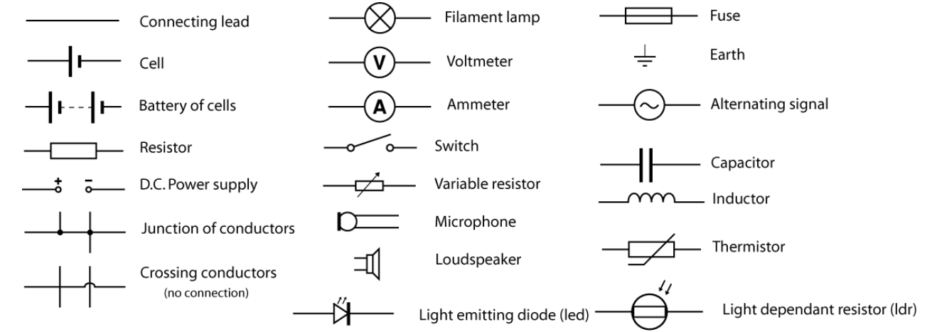
Circuit Symbols
Circuit Measuring Tools
Circuit measuring tools are used to measure various electrical parameters in a circuit.
These tools are essential for troubleshooting, testing, and designing circuits.
Multimeter: A versatile tool that can measure voltage, current, and resistance. It is used to troubleshoot circuits and check the continuity of wires and components. Multimeters come in both analog and digital versions.
Oscilloscope: Used to measure and display voltage signals over time. It is used to analyze waveforms and diagnose problems in circuits. Oscilloscopes come in both analog and digital versions.
Function generator: Used to generate various types of waveforms such as sine, square, and triangle waves. It is used to test circuits and simulate different types of signals.
Logic analyzer: Used to capture and analyze digital signals in a circuit. It is used to troubleshoot digital circuits and analyze the behavior of digital signals.
Power supply: Used to provide a constant voltage or current to a circuit. It is used to test circuits and power electronic devices.
LCR meter: Used to measure the inductance, capacitance, and resistance of a circuit. It is used to test and design circuits that use inductors, capacitors, and resistors.
Series Circuit
Series circuit: It is a circuit in which the components are connected in a single loop, so the current flows through each component in turn.
The components in a series circuit have the same current flowing through them.
The total resistance of a series circuit is equal to the sum of the individual resistances.
The voltage across each component in a series circuit is proportional to its resistance.
Parallel Circuit
Parallel circuit: It is a circuit in which the components are connected in separate branches, so the current divides between them.
The components in a parallel circuit have the same voltage across them.
The total resistance of a parallel circuit is less than the smallest individual resistance.
The current through each branch of a parallel circuit is proportional to the inverse of its resistance.
3.2: Power in a Circuit
Power is the rate at which energy is transferred or converted. In an electric circuit, power is the rate at which electrical energy is transferred from a power source to a device or load.
The formula for power in a circuit is:
P = VIwhere P is power, V is voltage, and I is current.
The unit of power is the watt (W). One watt is equal to one joule per second (J/s). Other units of power include kilowatts (kW) and megawatts (MW).
Calculating Power
To calculate power in a circuit, you need to know the voltage and current. Once you have these values, you can use the formula:
P = VIFor example, if a circuit has a voltage of 12 volts and a current of 2 amps, the power would be:
P = 12V x 2A = 24W
Power and Resistance
Power in a circuit is also related to resistance. The formula for power can be rewritten as:
P = I^2Ror
P = V^2/Rwhere R is resistance.
This shows that as resistance increases, power decreases. This is because more energy is lost as heat in the circuit due to the resistance.
3.3: Steady State Circuits
Kirchhoff's Voltage Law
Kirchhoff's Voltage Law (KVL) is a fundamental law in electrical engineering that states that the sum of all voltages around a closed loop in a circuit must be zero. This law is based on the principle of conservation of energy, which states that energy cannot be created or destroyed, only transferred from one form to another.
"The algebraic sum of all voltages around any closed loop in a circuit is equal to zero."
KVL is used to analyze and solve circuits that contain multiple voltage sources and resistors.
By applying KVL to a closed loop in a circuit, we can determine the voltage drop across each resistor and the voltage of each source.
KVL assumes that the circuit is a closed loop and that there are no changing magnetic fields within the loop.
In reality, circuits may contain changing magnetic fields, which can induce voltages that violate KVL.
In such cases, we need to use more advanced techniques, such as Kirchhoff's Current Law and Faraday's Law of Induction, to analyze the circuit.
Example of KVL
Consider the following circuit:
     +-----R1-----+

     |             |

    V1             R3

     |             |

     +-----R2-----+
Applying KVL to the loop formed by R1, R2, and R3, we get:
V1 - V(R1) - V(R2) - V(R3) = 0where V(R1), V(R2), and V(R3) are the voltage drops across resistors R1, R2, and R3, respectively.
Kirchhoff's Current Law
Kirchhoff's Current Law (KCL) is a fundamental law in electrical engineering that states that the total current entering a node or junction in a circuit must be equal to the total current leaving that node or junction.
In other words, the algebraic sum of all the currents entering and leaving a node must be zero.
KCL is based on the principle of conservation of charge, which states that charge cannot be created or destroyed, only transferred from one point to another.
KCL is applicable to both DC and AC circuits.
KCL is used to analyze and solve complex circuits by breaking them down into smaller parts and applying the law to each node or junction.
KCL can be expressed mathematically as: Σi(in) = Σi(out), where Σi(in) is the sum of all currents entering the node and Σi(out) is the sum of all currents leaving the node.
KCL is often used in conjunction with Kirchhoff's Voltage Law (KVL) to solve circuits.
Consider a simple circuit with three resistors connected in parallel to a voltage source. The current flowing through each resistor can be determined using KCL as follows:
At the junction where the resistors are connected, the total current entering the junction is equal to the total current leaving the junction.
Let's assume that the current flowing through the first resistor is I1, the current flowing through the second resistor is I2, and the current flowing through the third resistor is I3.
Applying KCL to the junction, we get: I1 + I2 + I3 = I_total
Since the resistors are connected in parallel, the voltage across each resistor is the same and can be calculated using Ohm's Law.
The total current flowing through the circuit can be calculated by summing the currents flowing through each resistor: I_total = I1 + I2 + I3.
Resistors in Series
When resistors are connected in series, they are connected end-to-end, so that the current flows through one resistor and then through the other.
The total resistance of the circuit is the sum of the individual resistances.
The formula for calculating the total resistance of resistors in series is:
R_total = R1 + R2 + R3 + ... + Rnwhere R1, R2, R3, ..., Rn are the individual resistances.
The current flowing through each resistor in a series circuit is the same, but the voltage across each resistor is different. The voltage across each resistor is proportional to its resistance.
Resistors in Parallel
When resistors are connected in parallel, they are connected across each other, so that the current flows through each resistor.
The total resistance of the circuit is less than the resistance of the smallest resistor.
The formula for calculating the total resistance of resistors in parallel is:
1/R_total = 1/R1 + 1/R2 + 1/R3 + ... + 1/Rnwhere R1, R2, R3, ..., Rn are the individual resistances.
The voltage across each resistor in a parallel circuit is the same, but the current flowing through each resistor is different.
The current flowing through each resistor is proportional to its conductance.
Non-Ideal Batteries
Real batteries are non-ideal and have internal resistance.
The internal resistance of a battery causes a voltage drop across the battery when a current flows through it.
The voltage across the terminals of a battery is less than its EMF due to this voltage drop.
The voltage drop across the internal resistance of a battery can be calculated using Ohm's law: V = IR, where V is the voltage drop, I is the current flowing through the battery, and R is the internal resistance of the battery.
Electromotive Force
EMF stands for electromotive force and is the voltage generated by a battery or other source of electrical energy.
EMF Equation
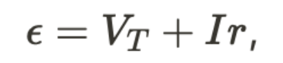
where r is the internal resistance of the battery.
The EMF of a battery is the maximum voltage that it can provide when no current is flowing through it.
The EMF of a battery is affected by factors such as temperature, the concentration of the electrolyte, and the materials used in the electrodes.
The EMF of a battery can be measured using a voltmeter connected across its terminals when no current is flowing through it.
3.4: Capacitors in a Circuit
Capacitors in Series
When capacitors are connected in series, the total capacitance is less than the capacitance of any individual capacitor. The formula for calculating the total capacitance of capacitors in series is:
1/C_total = 1/C_1 + 1/C_2 + ... + 1/C_nwhere
C_total is the total capacitance
C_1, C_2, ..., C_n are the capacitances of individual capacitors.
The voltage across each capacitor in series is proportional to its capacitance. The capacitor with the smallest capacitance will have the highest voltage across it.
Capacitors in Parallel
When capacitors are connected in parallel, the total capacitance is the sum of the capacitances of individual capacitors. The formula for calculating the total capacitance of capacitors in parallel is:
C_total = C_1 + C_2 + ... + C_nwhere:
**C_**total is the total capacitance
C_1, C_2, ..., C_n are the capacitances of individual capacitors.
The voltage across each capacitor in parallel is the same. The charge on each capacitor is proportional to its capacitance.
RC Circuits
RC circuits are circuits that contain a resistor and a capacitor. These circuits are used in a variety of applications, including filters, timing circuits, and oscillators.
Capacitor Charging
When a capacitor is connected to a voltage source through a resistor, it charges up to the voltage of the source.
The time it takes for the capacitor to charge up to 63.2% of the source voltage is given by the time constant, which is equal to the product of the resistance and the capacitance.

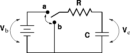
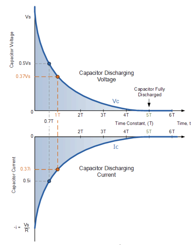
Capacitor Discharging
When a charged capacitor is disconnected from a voltage source and connected to a resistor, it discharges through the resistor.
The time it takes for the capacitor to discharge to 36.8% of its initial voltage is given by the time constant.
RC Filters
RC circuits can be used as filters to pass or block certain frequencies. A high-pass filter passes high frequencies and blocks low frequencies, while a low-pass filter passes low frequencies and blocks high frequencies. The cutoff frequency is the frequency at which the filter begins to attenuate the signal.
RC Oscillators
RC circuits can also be used as oscillators, which generate a periodic waveform. The frequency of the waveform is determined by the values of the resistor and capacitor in the circuit.
Unit 4: Magnetic Fields
4.1: Magnetic Fields
Magnetic fields: These are created by moving electric charges.
They are represented by lines of force that show the direction of the magnetic field.
The strength of the magnetic field is measured in tesla (T).
The magnetic field of a straight conductor can be determined using the right-hand rule.
If the right-hand thumb points in the direction of the current, the fingers will curl in the direction of the magnetic field.
The magnetic field of a circular conductor can be determined using the right-hand rule.
If the right-hand thumb points in the direction of the current, the fingers will curl in the direction of the magnetic field inside the loop.
Outside the loop, the magnetic field points in the opposite direction.
A solenoid is a coil of wire that produces a magnetic field when an electric current is passed through it.
The magnetic field inside a solenoid is uniform and parallel to the axis of the coil.
The strength of the magnetic field can be increased by increasing the number of turns in the coil or by increasing the current.
A bar magnet has two poles, a north pole and a south pole.
The magnetic field lines of a bar magnet extend from the north pole to the south pole.
The strength of the magnetic field is strongest at the poles and decreases as you move away from the magnet.
Right Hand Rule for Magnetic Fields
The right hand rule is a mnemonic technique used to determine the direction of a magnetic field in relation to the direction of the current flowing through a wire.
It is based on the principle that a magnetic field is created around a current-carrying wire.
How to use the right hand rule
Hold your right hand so that your thumb points in the direction of the current flow.
Curl your fingers around the wire in the direction of the magnetic field.
Your fingers will point in the direction of the magnetic field lines.
The right hand rule is used in various applications, including:
Determining the direction of the magnetic field around a current-carrying wire.
Determining the direction of the force on a current-carrying wire in a magnetic field.
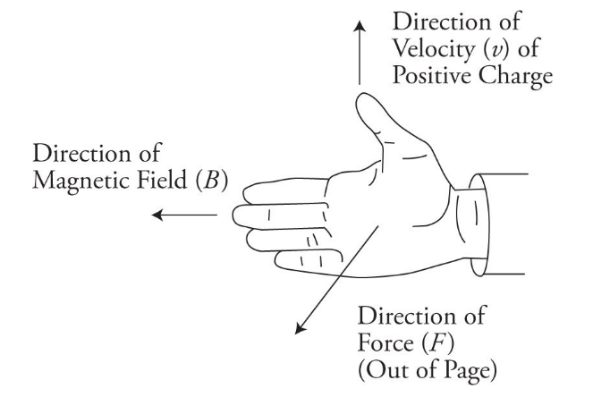
Determining the direction of the force on a charged particle moving in a magnetic field.
Magnetic & Electric Field Interactions
When a charged particle moves through a magnetic field, it experiences a force perpendicular to both the direction of motion and the magnetic field.
This is known as the Lorentz force and can be calculated using the equation:
F = q(v x B)where
F is the force
q is the charge of the particle
v is the velocity of the particle
B is the magnetic field.
Similarly, when a charged particle is placed in an electric field, it experiences a force in the direction of the electric field. This force can be calculated using the equation:
F = qEwhere
F is the force
q is the charge of the particle
E is the electric field.
When both magnetic and electric fields are present, the particle experiences a combined force that is the vector sum of the two individual forces. This can be calculated using the equation:
F = qE + q(v x B)
The interaction between magnetic and electric fields is important in many areas of physics, including particle accelerators, plasma physics, and astrophysics. It is also the basis for many technological applications, such as magnetic resonance imaging (MRI) and particle detectors.
4.2: Current-Carrying Wires & Magnetic Field
Forces on a Wire in an External Magnetic Field
When a wire carrying current is placed in an external magnetic field, it experiences a force. This force is known as the Lorentz force and is given by the equation:
F = I L x Bwhere
F is the force
I is the current in the wire
L is the length of the wire in the magnetic field
B is the magnetic field strength.
The direction of the force is given by the right-hand rule. If the thumb of the right hand points in the direction of the current, and the fingers point in the direction of the magnetic field, then the palm of the hand will point in the direction of the force.
If the wire is not perpendicular to the magnetic field, then only the component of the magnetic field perpendicular to the wire will cause a force. This component is given by:
B_perp = B sin(theta)where theta is the angle between the wire and the magnetic field.
If the wire is part of a closed loop, then the forces on each segment of the wire will cancel out, except for the segments at the ends of the loop. These segments will experience a net force and will move in a circular path. This is the principle behind the electric motor.
Torque on a Wire
When a wire is twisted, a torque is applied to it. This torque is proportional to the force applied and the distance from the axis of rotation. The torque can be calculated using the formula:
T = F * r * sin(theta)where
T is the torque
F is the force applied
r is the distance from the axis of rotation,
theta is the angle between the force and the radius vector.
The direction of the torque is perpendicular to both the force and the radius vector, and follows the right-hand rule. If the fingers of the right hand are curled in the direction of the force, and the thumb points in the direction of the radius vector, then the direction of the torque is given by the direction in which the thumb points.
The torque on a wire can be used to measure the torsional stiffness of the wire. By measuring the angle of twist and the applied torque, the torsional stiffness can be calculated using the formula:
k = T / thetawhere
k is the torsional stiffness
theta is the angle of twist.
The torsional stiffness of a wire depends on its material properties, such as its modulus of elasticity and its cross-sectional area. It also depends on the length and diameter of the wire, as well as the method of twisting.
Magnetic Fields From a Current Carrying Wire
When an electric current flows through a wire, it generates a magnetic field around the wire. This magnetic field can be visualized using magnetic field lines, which show the direction and strength of the magnetic field at different points around the wire.
The direction of the magnetic field around a current-carrying wire can be determined using the right-hand rule. If you point your right thumb in the direction of the current flow, the direction of the magnetic field lines can be determined by the direction your fingers curl around the wire.
The strength of the magnetic field around a current-carrying wire depends on the amount of current flowing through the wire and the distance from the wire. The magnetic field strength decreases as the distance from the wire increases.
A solenoid is a coil of wire that is wrapped around a cylindrical object, such as a metal rod. When a current flows through the wire, it generates a magnetic field that is concentrated inside the coil. The strength of the magnetic field can be increased by increasing the number of turns in the coil or by increasing the current flowing through the wire.
Magnetic Field Produced by a Current-Carrying Wire
A current-carrying wire produces a magnetic field around it.
The direction of the magnetic field can be determined using the right-hand rule.
If the thumb of the right hand points in the direction of the current, the fingers curl in the direction of the magnetic field.
Force Between Two Parallel Current-Carrying Wires
When two parallel wires carrying current in the same direction are placed close to each other, they experience a force of attraction.
This is because the magnetic fields produced by the currents in the wires are in the same direction and interact with each other.
When two parallel wires carrying current in opposite directions are placed close to each other, they experience a force of repulsion.
This is because the magnetic fields produced by the currents in the wires are in opposite directions and interact with each other.
The force between the wires can be calculated using the formula:
F = μ₀I₁I₂L / 2πdwhere
F is the force
μ₀ is the permeability of free space
I₁ and I₂ are the currents in the wires
L is the length of the wires
d is the distance between the wires.
Drawing Magnetic Fields
Direction of the field: Magnetic field lines always point from the north pole of a magnet to the south pole. In the case of a current-carrying wire, the direction of the magnetic field can be determined using the right-hand rule.
Strength of the field: The strength of the magnetic field is indicated by the density of the field lines. The closer together the lines are, the stronger the field.
Shape of the field: The shape of the magnetic field depends on the shape of the magnet or current-carrying wire. For example, the field around a straight wire is circular, while the field around a loop of wire is more complex.
Magnetic field inside vs. outside: In general, magnetic fields are stronger closer to the source (i.e. the magnet or wire) and weaker further away. However, the exact shape of the field can vary depending on the geometry of the source.
Interactions with other fields: Magnetic fields can interact with electric fields and with other magnetic fields. These interactions can lead to complex patterns of field lines and can be used to create a wide range of devices, from electric motors to MRI machines.
4.3: Biot–Savart Law and Ampère’s Law
Biot-Savart Law
The Biot-Savart Law is a fundamental law in electromagnetism that describes the magnetic field produced by a current-carrying wire. It was discovered by Jean-Baptiste Biot and Felix Savart in 1820.
The Biot-Savart Law states that the magnetic field at a point is proportional to the current density and the distance from the point to the current element. The direction of the magnetic field is perpendicular to both the current element and the vector from the current element to the point.
Mathematically, it is written as:

where
B is magnetic field intensity
μ₀ is permeability of free space
N is number of turns
I is current intensity
R is radius
The Biot-Savart Law is used to calculate the magnetic field produced by a current-carrying wire or a group of wires. It is also used in the calculation of the magnetic field of a solenoid, a toroid, and other complex geometries.
The Biot-Savart Law is only valid for steady currents and does not take into account the effects of changing electric fields. It also assumes that the current density is constant throughout the wire, which may not be the case in practice.
Biot-Savart Law Sample Problem
A long straight wire carries a current of 5 A. Find the magnetic field at a point 3 cm away from the wire.
Solution
The formula for the magnetic field due to a current-carrying wire is given by:
B = (μ₀ * I)/(2πr)where
Bis the magnetic field,Iis the current,ris the distance from the wire, andμ₀is the permeability of free space.
Substituting the given values in the formula, we get:
B = (4π * 10^-7 * 5)/(2π * 0.03)B = 3.33 * 10^-5 T
Therefore, the magnetic field at a point 3 cm away from the wire carrying a current of 5 A is
3.33 * 10^-5 T.
Ampère's Law
Ampère's Law is a fundamental law of electromagnetism that relates the magnetic field around a closed loop to the electric current passing through the loop. The law was discovered by André-Marie Ampère in 1826.
The law states that the line integral of the magnetic field around a closed loop is equal to the current passing through the loop multiplied by a constant known as the permeability of free space.
Mathematically, the law can be expressed as:
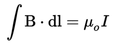
where
B is the magnetic field
dl is an infinitesimal element of the loop
μ₀ is the permeability of free space
I is the current passing through the loop.
Ampère's Law Sample Problem
A long, straight wire carries a current of 10 A. What is the magnetic field at a distance of 5 cm from the wire?
Solution
We can use Ampère's Law to solve this problem. Ampère's Law states that the line integral of the magnetic field around a closed loop is equal to the current passing through the loop multiplied by the permeability of free space.
We can choose a circular loop of radius 5 cm around the wire. The magnetic field at every point on the loop is parallel to the tangent at that point. Therefore, the line integral of the magnetic field around the loop is simply the product of the magnetic field and the circumference of the loop.
The current passing through the loop is equal to the current in the wire, which is 10 A.
Therefore, we have:
B * 2πr = μ0 * Iwhere B is the magnetic field, r is the radius of the loop, μ0 is the permeability of free space, and I is the current passing through the loop.
Substituting the given values, we get:
B * 2π(0.05) = 4π * 10^-7 * 10
B = 2 * 10^-6 T
Therefore, the magnetic field at a distance of 5 cm from the wire is 2 * 10^-6 T.
Unit 5: Electromagnetism
5.1: Electromagnetism
Electromagnetic Induction
Electromagnetic induction: It is the process of generating an electromotive force (EMF) or voltage across a conductor by exposing it to a changing magnetic field. This phenomenon was discovered by Michael Faraday in 1831.
Electromagnetic induction has numerous practical applications, including:
Generators and alternators: These devices use electromagnetic induction to convert mechanical energy into electrical energy.
Transformers: These devices use electromagnetic induction to transfer electrical energy from one circuit to another.
Induction heating: This process uses electromagnetic induction to heat a metal object by inducing eddy currents within it.
Magnetic levitation: This technology uses electromagnetic induction to levitate an object above a magnetic surface.
Magnetic Flux
Magnetic flux: It is the measure of the strength of a magnetic field passing through a given area. It is denoted by the symbol Φ and is measured in Weber (Wb) or Tesla meter squared (Tm²).
The formula for magnetic flux is:
Φ = B * A * cos(θ)where:
Φ is the magnetic flux
B is the magnetic field strength
A is the area of the surface
θ is the angle between the magnetic field and the surface normal
The SI unit of magnetic flux is Weber (Wb) or Tesla meter squared (Tm²). One Weber is equal to one Tesla meter squared.
Magnetic flux is used in various applications such as:
Electric generators
Transformers
Inductors
Magnetic sensors
Magnetic levitation systems
Faraday's Law
Faraday's Law of Electromagnetic Induction states that a changing magnetic field induces an electromotive force (EMF) in a conductor. This law was discovered by Michael Faraday in 1831.
This law is expressed mathematically as:
EMF = -dΦ/dtwhere EMF is the electromotive force, Φ is the magnetic flux, and t is time.
The negative sign indicates that the induced EMF opposes the change in magnetic flux.
The unit of EMF is volts (V).
The unit of magnetic flux is webers (Wb).
The unit of time is seconds (s).
Key Concepts
A magnetic field is created by a moving electric charge.
A changing magnetic field induces an EMF in a conductor.
The induced EMF creates an electric current in the conductor.
The magnitude of the induced EMF is proportional to the rate of change of the magnetic field.
The direction of the induced EMF is such that it opposes the change in the magnetic field that produced it. This is known as Lenz's Law.
Faraday's Law has numerous applications in modern technology, including:
Generators: Electrical generators use Faraday's Law to convert mechanical energy into electrical energy.
Transformers: Transformers use Faraday's Law to transfer electrical energy from one circuit to another.
Induction cooktops: Induction cooktops use Faraday's Law to heat up cooking vessels.
Magnetic levitation: Magnetic levitation trains use Faraday's Law to levitate above the tracks.
Faraday's Law has some limitations, including:
The conductor must be in motion relative to the magnetic field to induce an EMF.
The conductor must be part of a closed circuit for an electric current to flow.
The induced EMF is proportional to the rate of change of the magnetic field, so a steady magnetic field will not induce an EMF.
Lenz's Law
Lenz's Law is a fundamental law of electromagnetism that describes the direction of the induced electromotive force (EMF) and current that is generated in a conductor when it is exposed to a changing magnetic field.
The law states that the direction of the induced EMF and current is such that it opposes the change that produced it.
The formula for Lenz's law is given by:
ε = -dΦ/dtwhere
ε is the induced EMF
Φ is the magnetic flux
t is time.
The negative sign indicates that the induced EMF is in the opposite direction to the change in magnetic flux.
This means that when a magnetic field is applied to a conductor, the induced current will flow in a direction that creates a magnetic field that opposes the original magnetic field.
Lenz's Law is based on the principle of conservation of energy, which states that energy cannot be created or destroyed, only transformed from one form to another.
The law has many practical applications, including in the design of electric generators and motors, transformers, and in the braking systems of trains and other vehicles.
Lenz's Law is also used in the study of electromagnetic waves and the behavior of charged particles in magnetic fields.
The law was first formulated by the Russian physicist Heinrich Lenz in 1834, and it is one of the basic laws of electromagnetism.
5.2: Inductance
Inductance is a property of an electrical circuit that opposes changes in current. It is measured in henries (H) and is represented by the symbol L.
Inductance is created when a current flows through a conductor, generating a magnetic field around it.
This magnetic field stores energy, which opposes any changes in the current that created it.
When the current changes, the magnetic field changes as well, and the energy stored in the field is released, creating a voltage that opposes the change in current.
Inductance is used in a variety of electrical devices, including transformers, motors, and generators. It is also used in electronic filters to block certain frequencies of signals.
Calculation of Inductance
The inductance of a circuit can be calculated using the formula:
L = NΦ/IWhere
L is the inductance in henries
N is the number of turns in the coil
Φ is the magnetic flux through the coil
I is the current flowing through the coil
Energy Stored in an Inductor
An inductor is a passive electronic component that stores energy in a magnetic field when an electric current flows through it. The energy stored in an inductor can be calculated using the following formula:
W = 1/2 * L * I^2Where
W is the energy stored in joules
L is the inductance of the inductor in henries
I is the current flowing through the inductor in amperes.
The energy stored in an inductor is proportional to the square of the current flowing through it. This means that the energy stored in an inductor can be increased by increasing the current flowing through it.
When the current flowing through an inductor is interrupted, the magnetic field collapses and the energy stored in the inductor is released. This can cause a voltage spike, which can damage electronic components if not properly controlled.
Inductors are commonly used in electronic circuits to filter out unwanted signals, store energy, and regulate voltage. Understanding the energy stored in an inductor is important for designing and analyzing electronic circuits.
LR Circuit Behavior
An LR circuit is a circuit that consists of a resistor (R) and an inductor (L) connected in series. When a voltage is applied to the circuit, the current that flows through the circuit changes over time due to the inductor's behavior.
When a voltage is applied to an LR circuit, the current initially increases, but the inductor resists the change in current flow.
As a result, the current eventually reaches a steady state value.
The time it takes for the current to reach the steady state value is determined by the time constant of the circuit, which is equal to the inductance divided by the resistance.
When the voltage is removed from the circuit, the inductor releases the energy stored in its magnetic field, which causes the current to continue to flow for a short period of time. This is known as the inductor's back EMF (electromotive force).
LR circuits are commonly used in electronic devices such as power supplies, filters, and oscillators. They are also used in electric motors and generators to control the flow of current and generate magnetic fields.
LC Circuit Behavior
An LC circuit is a type of resonant circuit consisting of an inductor (L) and a capacitor (C) connected together.
When an LC circuit is charged, the capacitor stores energy in the form of an electric field, while the inductor stores energy in the form of a magnetic field.
The energy oscillates back and forth between the capacitor and the inductor, resulting in a resonant frequency.
The resonant frequency of an LC circuit is given by the formula:
f = 1 / (2π√LC)where f is the resonant frequency, L is the inductance of the inductor, and C is the capacitance of the capacitor.
At the resonant frequency, the impedance of the circuit is at a minimum, and the current is at a maximum.
When an LC circuit is first charged, the capacitor begins to store energy in the form of an electric field.
As the capacitor charges, the current in the circuit increases, causing the magnetic field in the inductor to increase.
When the capacitor is fully charged, the current in the circuit reaches its maximum value, and the magnetic field in the inductor is at its maximum.
As the capacitor begins to discharge, the current in the circuit decreases, causing the magnetic field in the inductor to decrease.
When the capacitor is fully discharged, the current in the circuit reaches zero, and the magnetic field in the inductor is at its minimum.
The energy stored in the magnetic field is then transferred back to the capacitor, and the cycle repeats.
LC circuits are used in a variety of applications, including:
Radio tuning circuits
Oscillators
Filters
Voltage regulators
In radio tuning circuits, LC circuits are used to select a specific frequency from a range of frequencies. In oscillators, LC circuits are used to generate a stable frequency.
In filters, LC circuits are used to pass or block certain frequencies. In voltage regulators, LC circuits are used to smooth out fluctuations in voltage.
5.3: Maxwell’s Equations
Maxwell's equations are a set of four fundamental equations that describe the behavior of electric and magnetic fields.
These equations were developed by James Clerk Maxwell in the 19th century and are considered one of the most important contributions to the field of electromagnetism.
Gauss's Law for Electric Fields
This equation states that the electric flux through any closed surface is proportional to the charge enclosed within the surface. In mathematical terms, it can be written as:
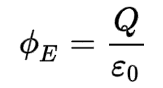
where
Φ is electric flux through a closed surface S enclosing any volume V
Q is total charge enclosed within V
ε0 is electric constant
Gauss's Law for Magnetic Fields
This equation states that the magnetic flux through any closed surface is zero. In mathematical terms, it can be written as:
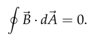
There are no magnetic charges. Magnetic field lines always close in themselves.
Faraday's Law of Electromagnetic Induction
This equation states that a changing magnetic field induces an electric field. In mathematical terms, it can be written as:
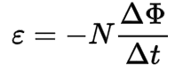
where
ε is induced voltage
N is number of loops
Δ ϕ is change in magnetic flux
Δ t is change in time
Ampere's Law with Maxwell's Correction
This equation relates the magnetic field to the current density and the rate of change of the electric field. In mathematical terms, it can be written as: