Tags & Description
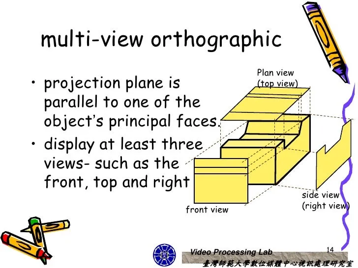
Orthographic Projection
The exact representation of a figure
Process of representing 3d objects in 2d
Multiview Projection, Parallel Projection
Other terms of Orthographic Projection
Ortho-
Means straight, upright, vertical (Came from Greek word 'orthos' meaning straight, right, true)
Graphic
marked by clear lifelike or vividly realistic description.
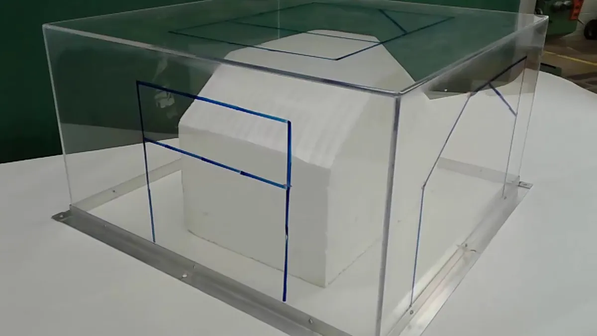
Glass Box
unfolding and transferring the height, width, and depth
3 Principal Views
Front View Top View Right Side View
3 Principal Planes
Frontal Plane Horizontal Plane Profile Plane
Working Drawing
used as a reference or guide in the manufacture of a product.
Assembly Drawing
[a part of working drawing dealing with] drawing various parts of a machine or structure assembled in their relative working positions.
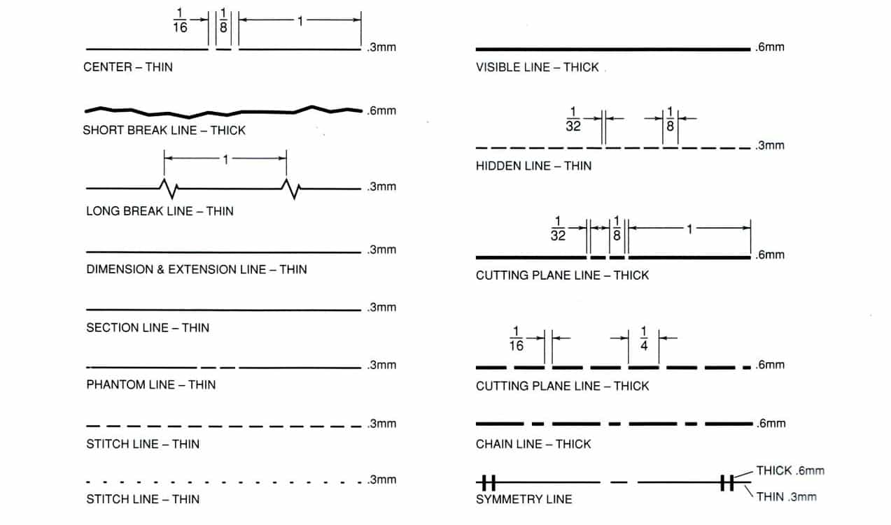
Alphabet of Lines
a list of line symbols that engineers and draftsmen use in technical drawings to communicate specific shapes, sizes or surfaces.
Construction Lines
used to construct layout work (guidelines)
thin and very light, should not be erased
Visible Lines
show outline of object, visible edges and surfaces.
thick and heavy
Section Lines
medium lines drawn at 45 degrees
show interior view of solid areas of cutting plane line.
Hidden Lines
short dash lines
show non visible surfaces.
Center Lines
long and short dash lines
usually indicates center of holes, circles and arcs
thin and dark
Dimension Lines
show the size of an object with a numeric value usually located in the middle of the line
usually with arrowheads or tick markings.
thin and dark
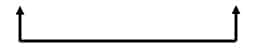
Extension Lines
show the starting and ending of dimension.
thin and dark
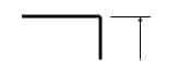
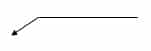
Leader Lines
-medium line with arrowhead
show label for size (e.g., radii) or special information about a feature.
Cutting Plane Lines
extra thick lines
show cutaway views or plane of projection where a section view is taken
arrow indicates the direction of view.
Short Break Lines Long Break Lines
short and long medium line use to show cutaway view of a long section.
SBL are used when the hidden part is rather short, while LBL are used when it's longer
Dimensioning
The process of adding size to a drawing information
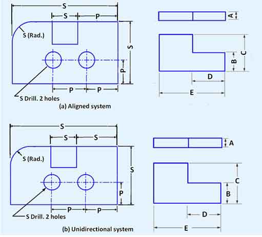
Aligned Dimensioning Unidirectional Dimensioning
Two systems of Dimensioning
Aligned Dimensioning
numbers are aligned with the side of the feature being measured
if dimension lines are drawn vertically on the right side of a drawing, the numerals would be flipped on its right
dimension is written in two directions
Unidirectional Dimensioning
reads from the bottom of the sheet and writes all numbers horizontally
dimension is written in the same direction in the whole drawing
Arc
curved line that is a part of a circle
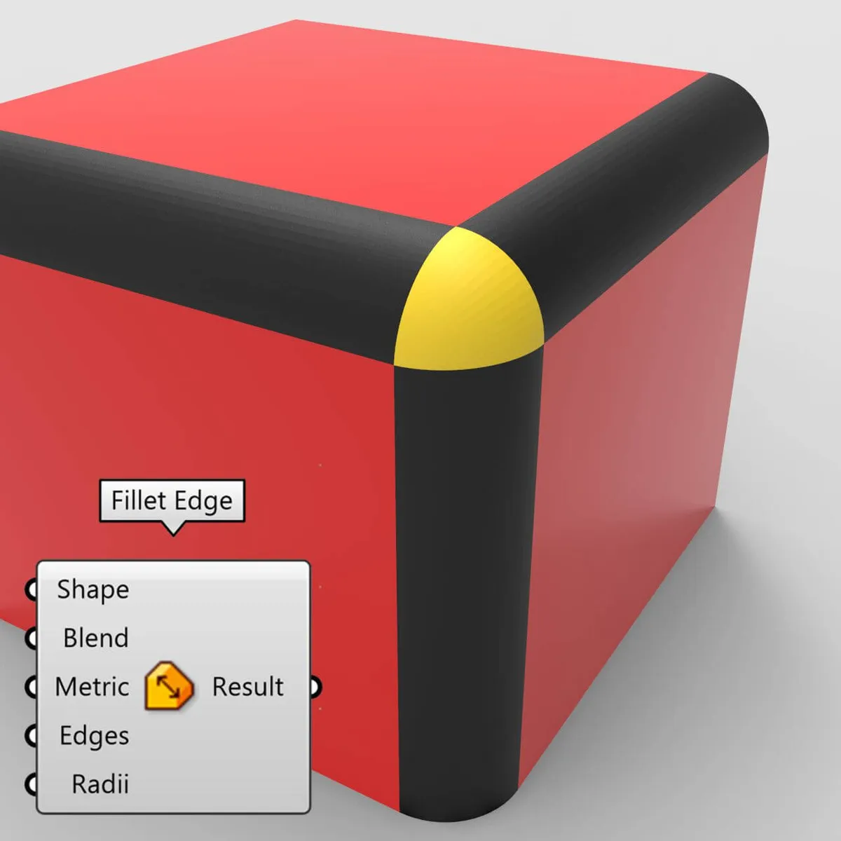
Fillet
rounded sides of a polygon's vertices -ex. tables with rounded corners
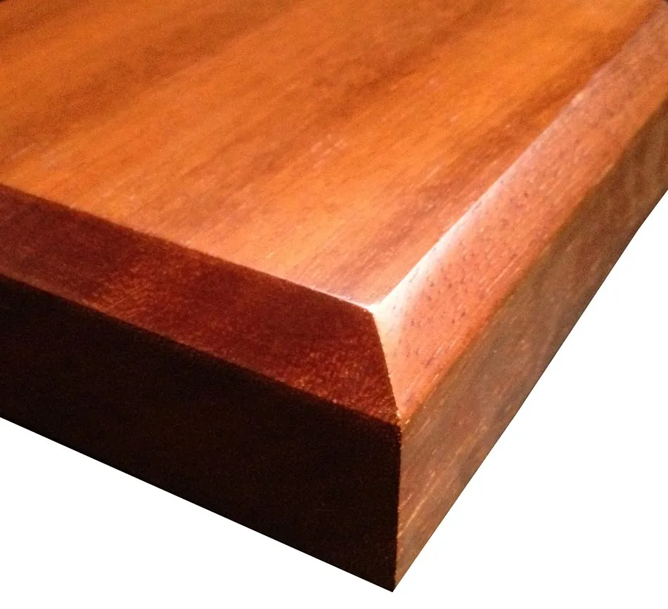
Chamfer
the sloped or angled edges or corners of a part design
straight and sharp angle, opposite of fillet