Absolute Coordinates
Identify the location in terms of distance from the origin (0,0,0) in each direction of the Cartesian coordinate system (x,y,z).
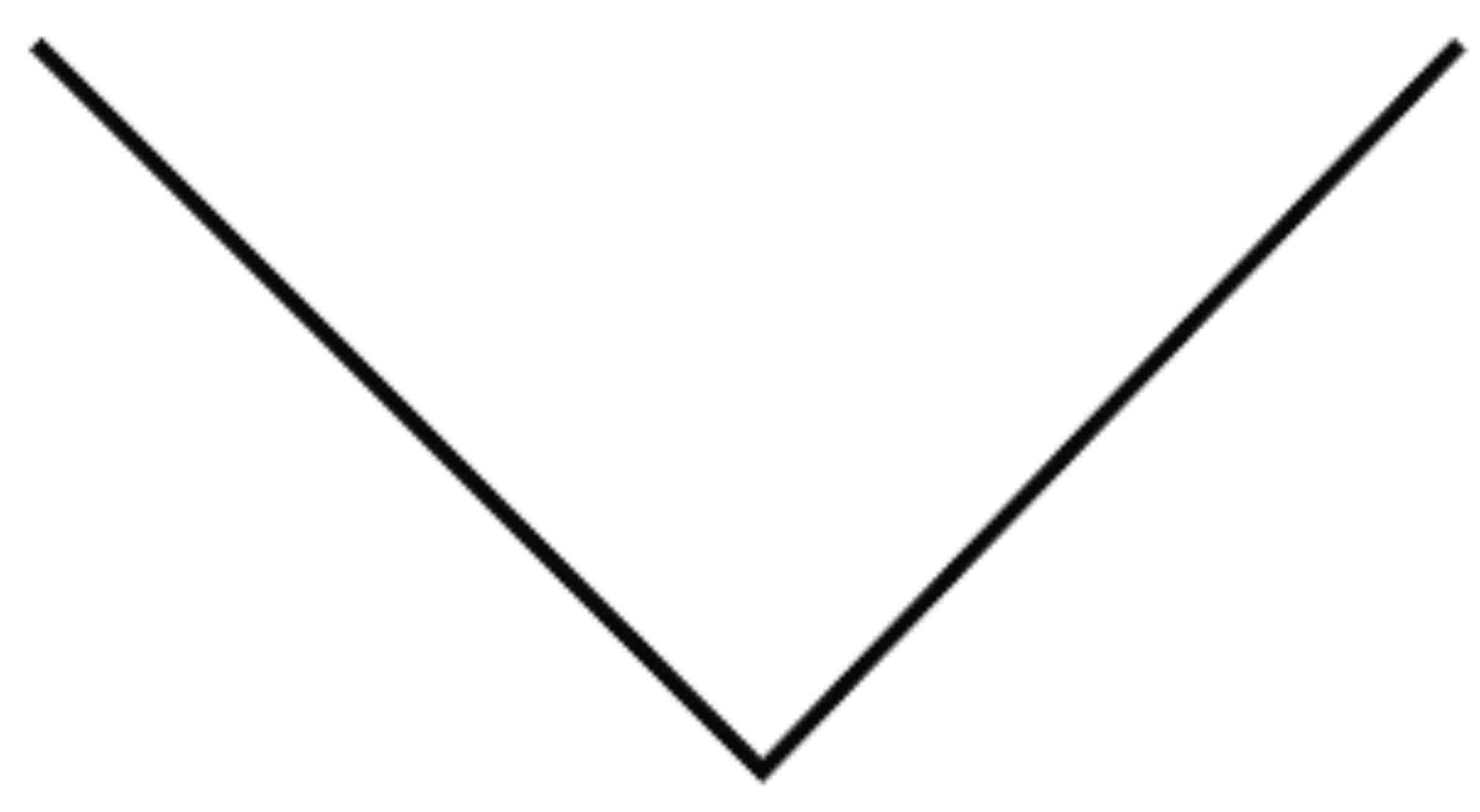
Polar Coordinate
Used to locate an object by providing an angle from the x-axis and a distance from the origin (0,0,0).
Cylindrical Coordinate
Specifies a 3D location based on a radius, angle, and distance from the origin (0,0,0)
Spherical Coordinate
Engineering Design Process
Ideation
Testing
Refinement
Production
Line Thicknesses
Very thick
Thick
Medium
Thin
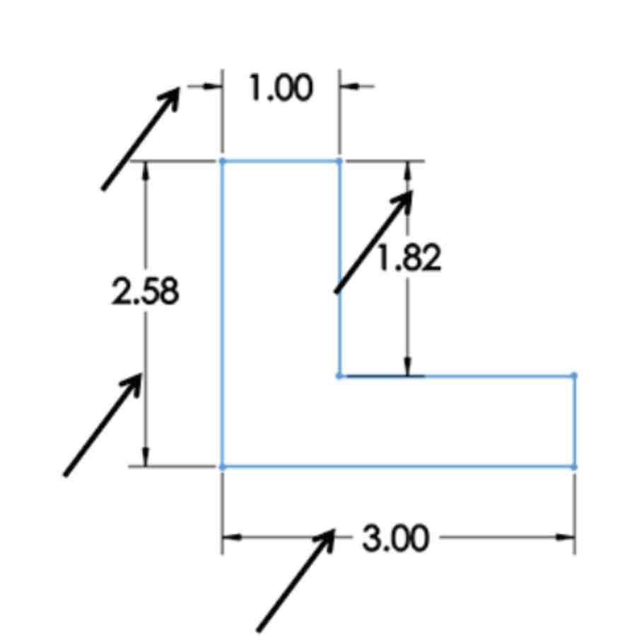
Visible/Feature Line
Continuous lines used to represent visible edges.
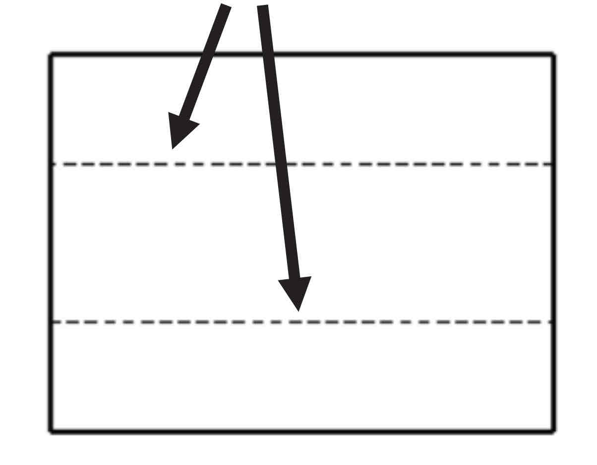
Hidden Line
Dashed line that represents hidden features.
Dimension LIne
Shows the extent and direction of the dimensions.
Extension Line
Does not touch the object.
Leader Line
Continuous straight line that extends for a note, arrowhead touches the feature.
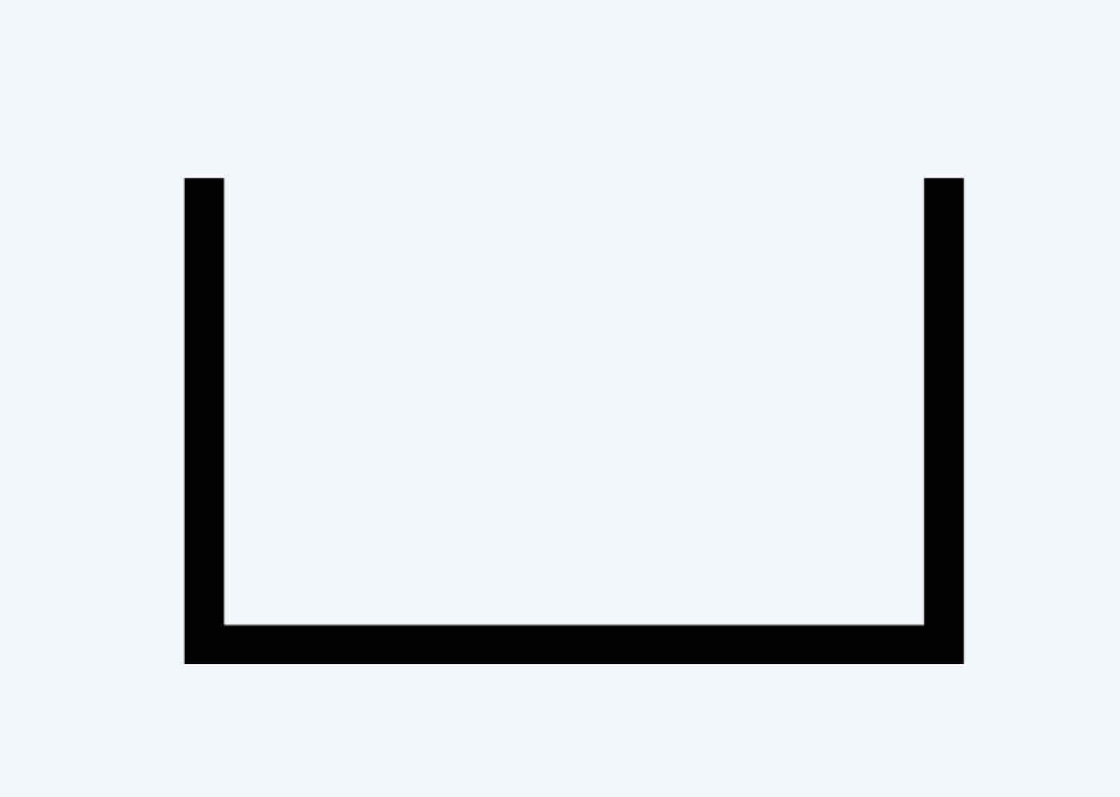
Break Line
Represents an imaginary cut. Allows the inside of the object to be viewed.
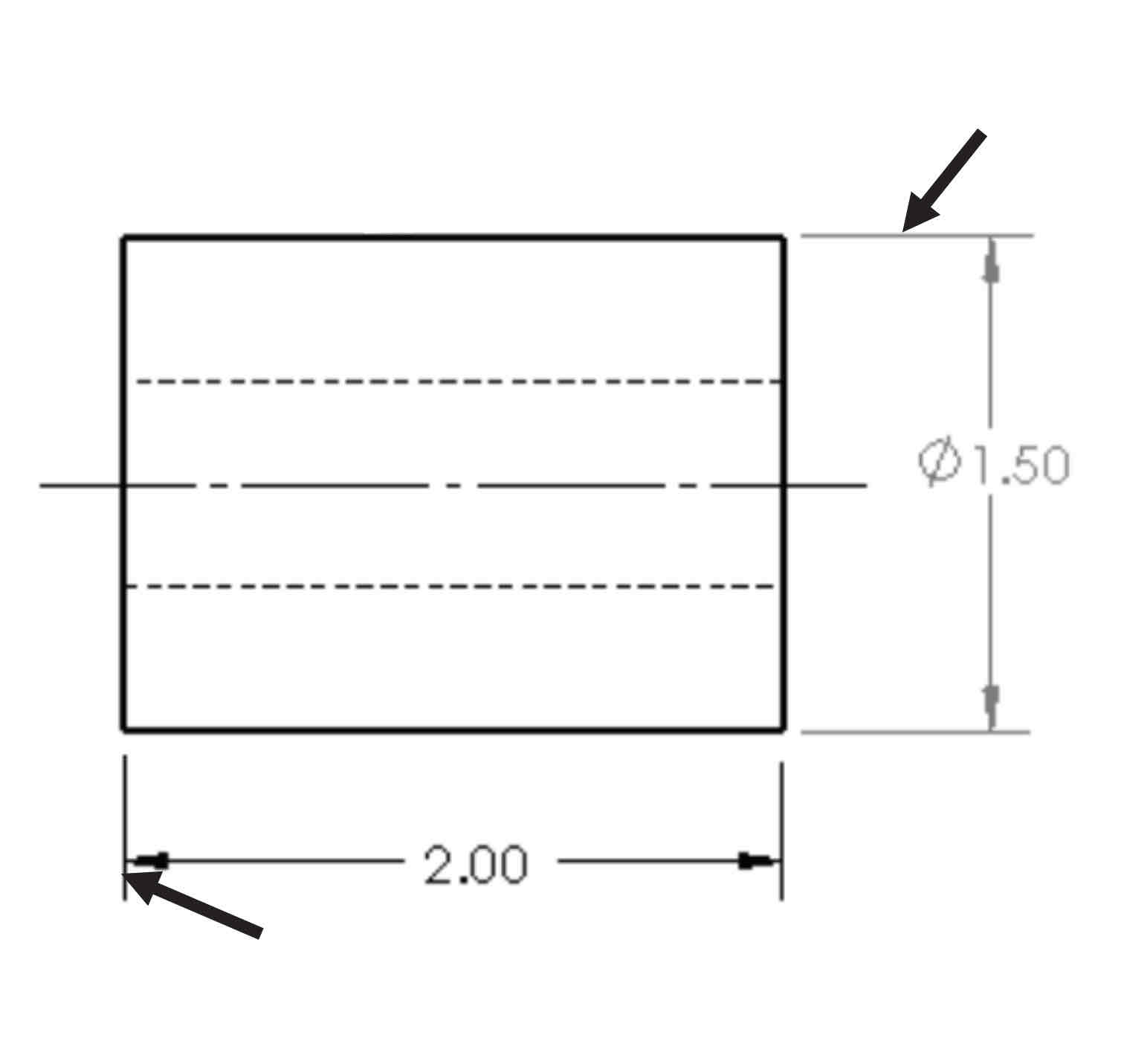
Center Line
Thin, long and short lines that represents the axis of symmetrical parts.
Phantom Line
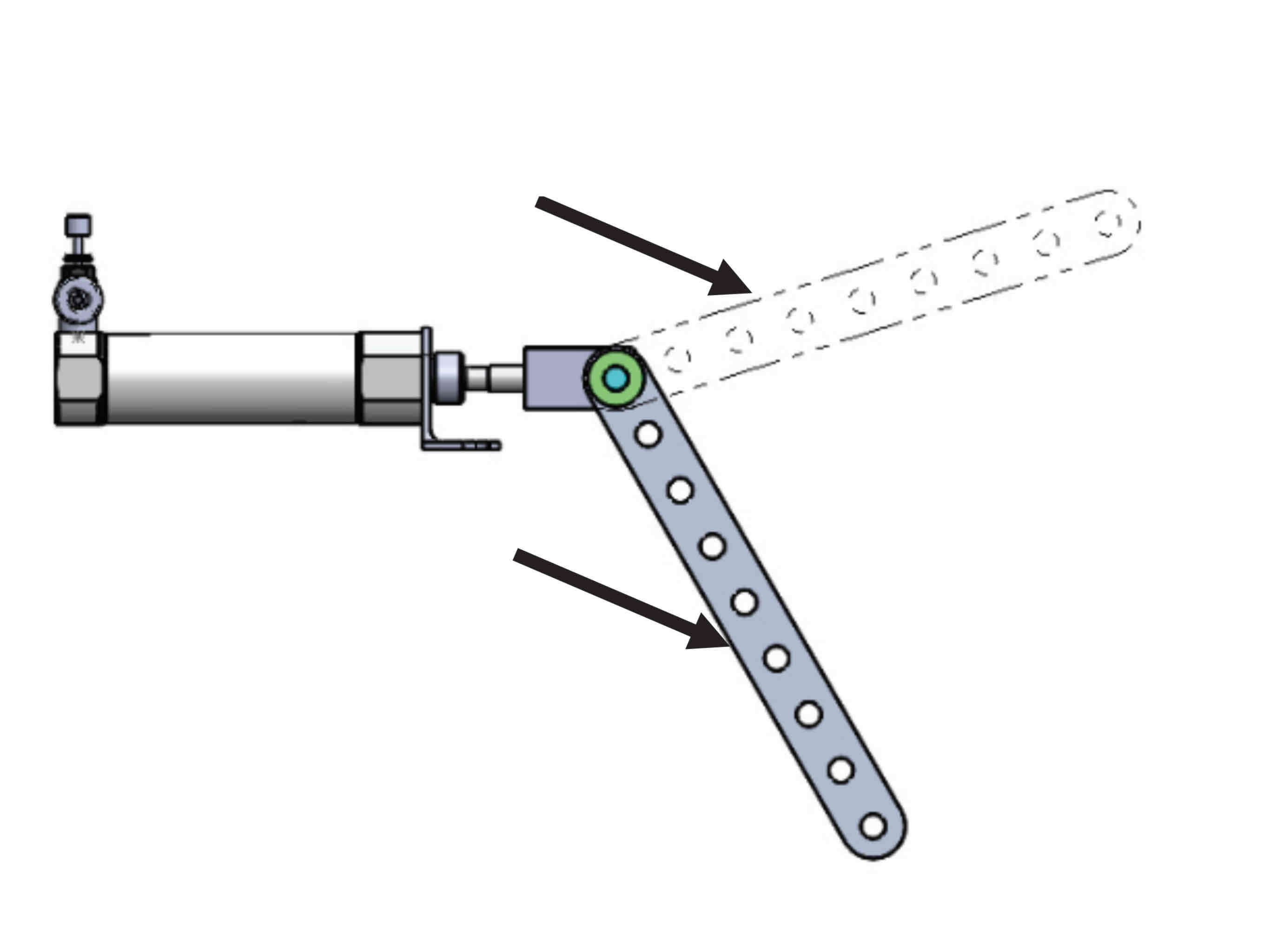
Represent alternate positions of moving parts, adjacent positions, and repeated details.
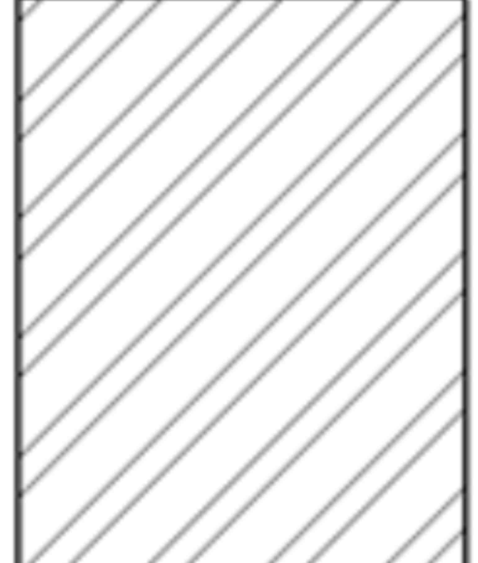
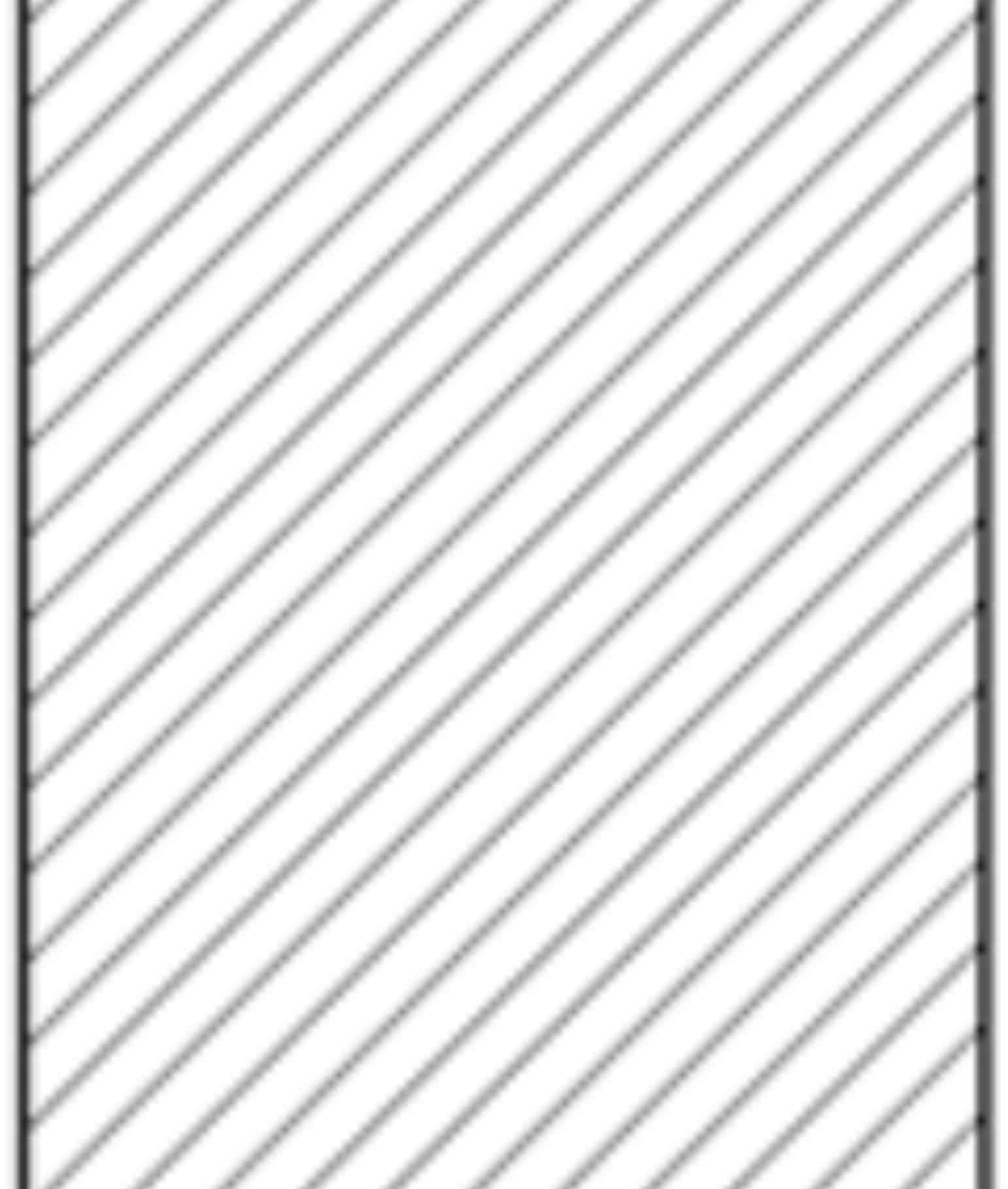
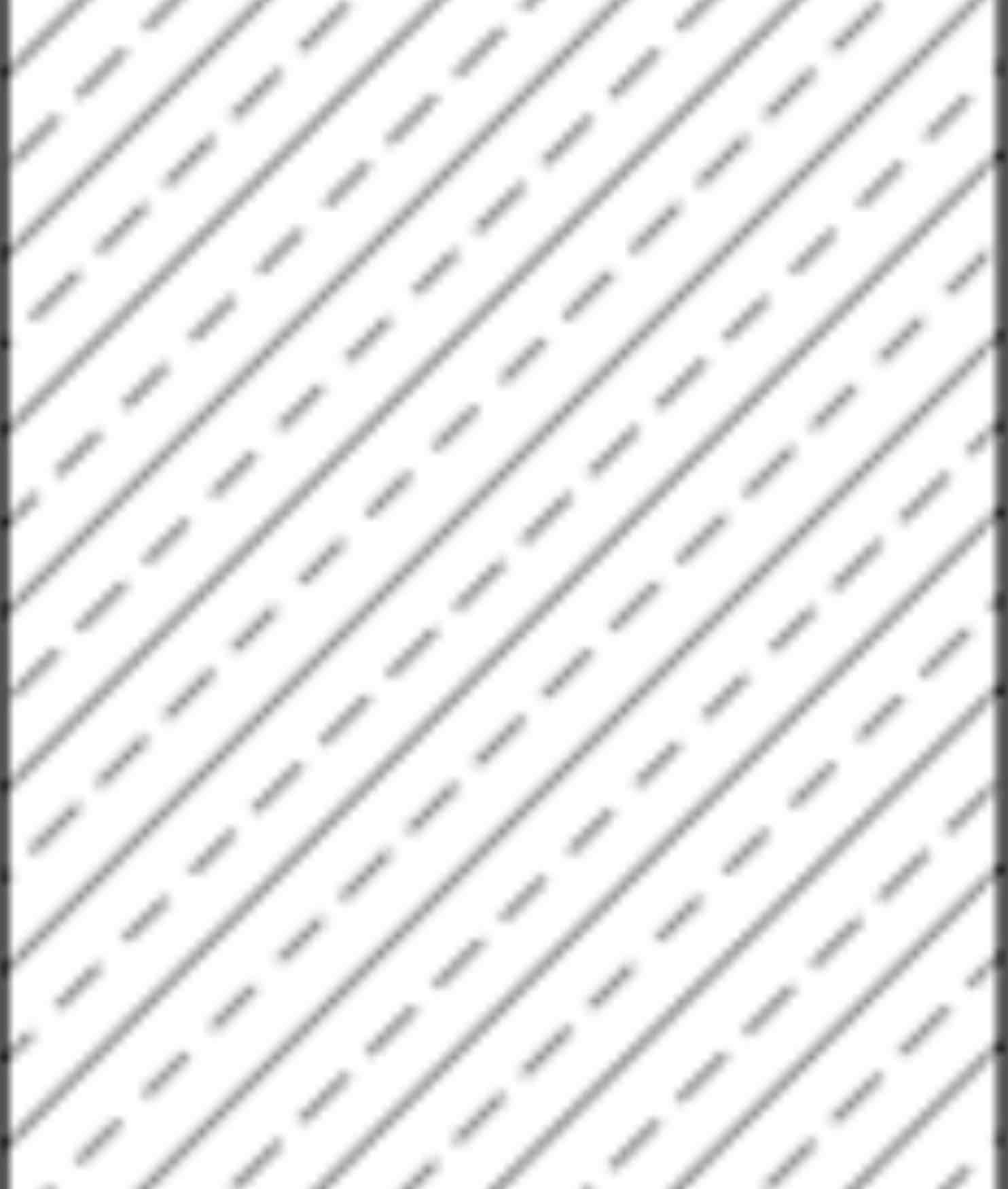
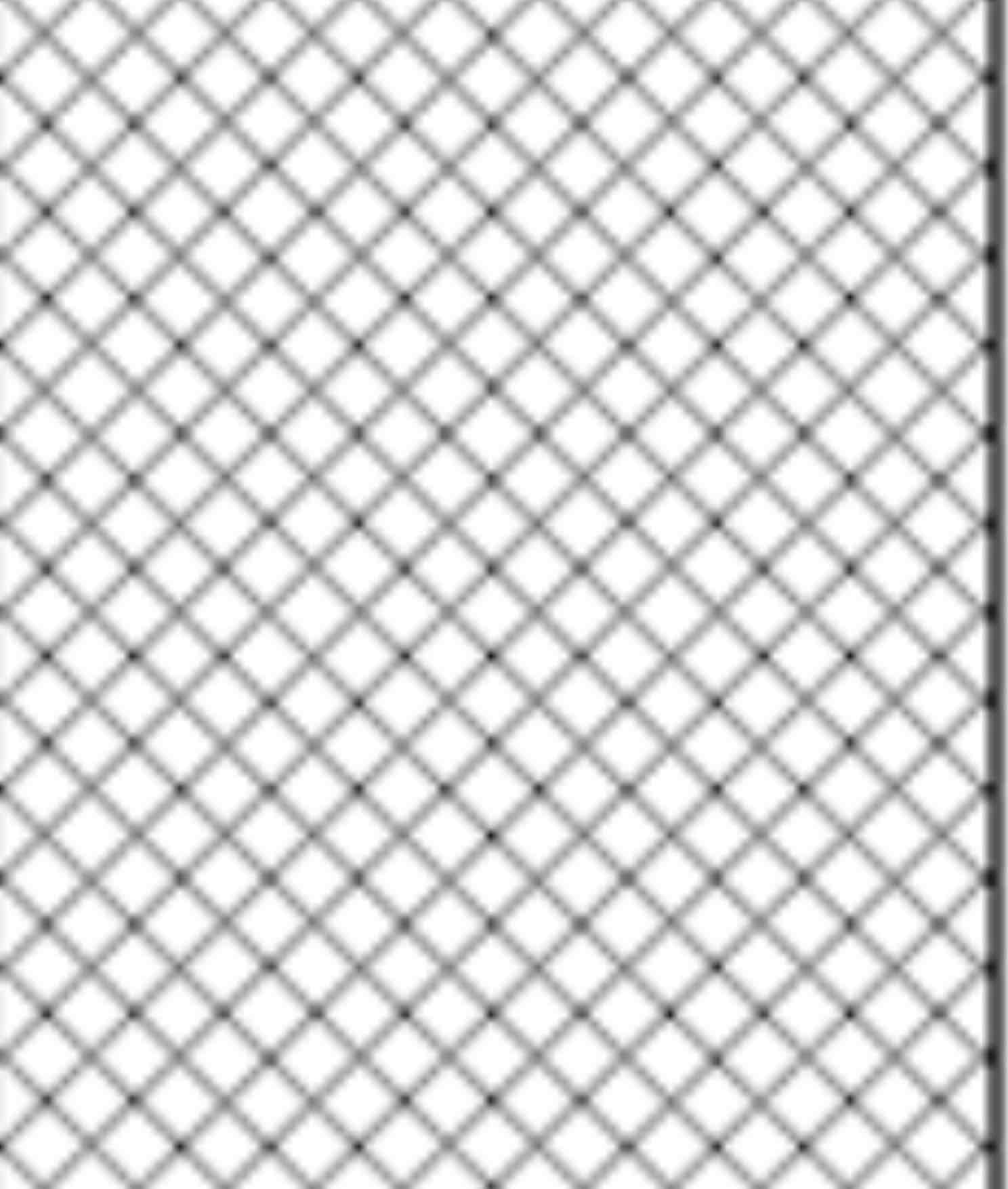
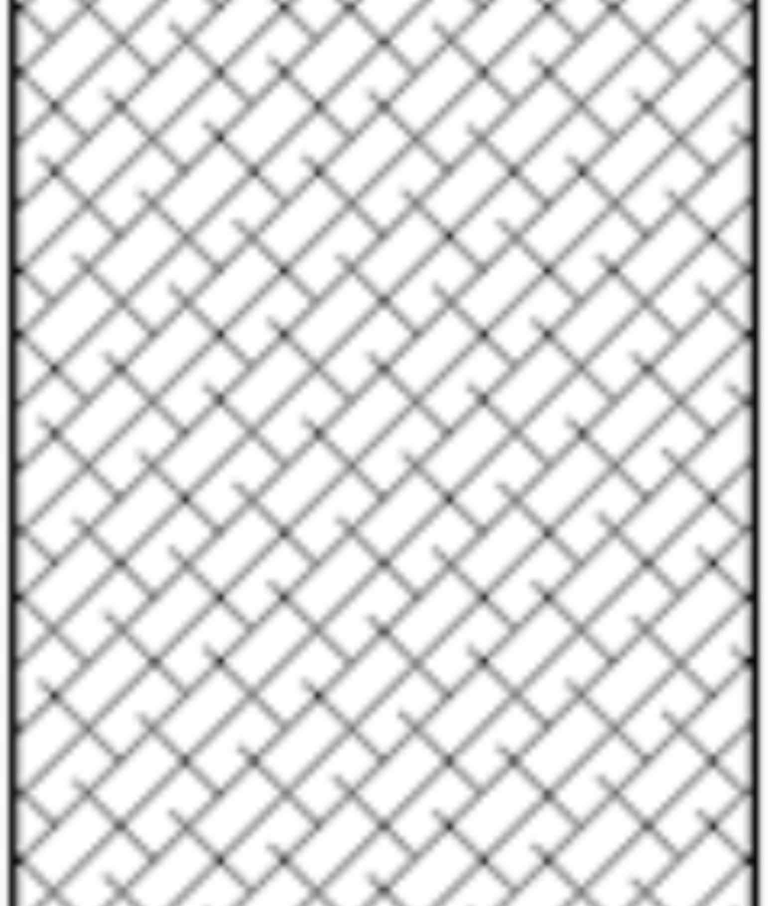
Section Line
Thin, uniformly spaced lines that indicate exposed cut surfaces of an object in a sectional view.
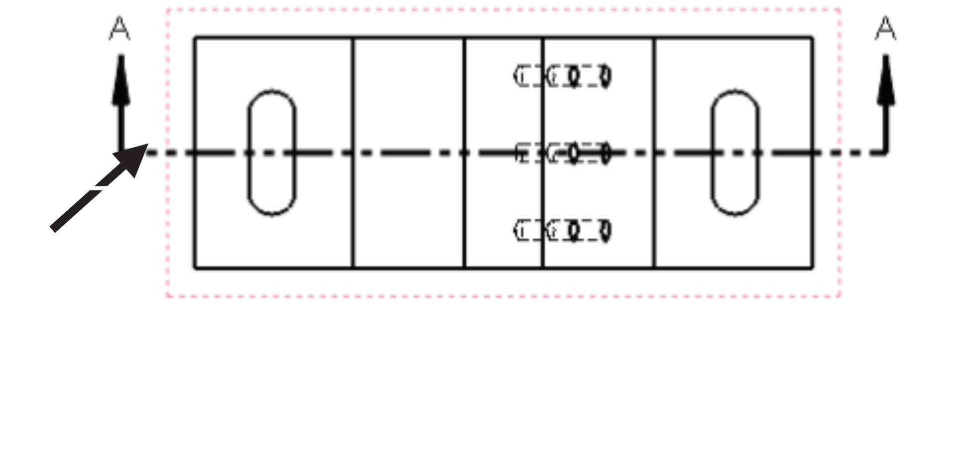
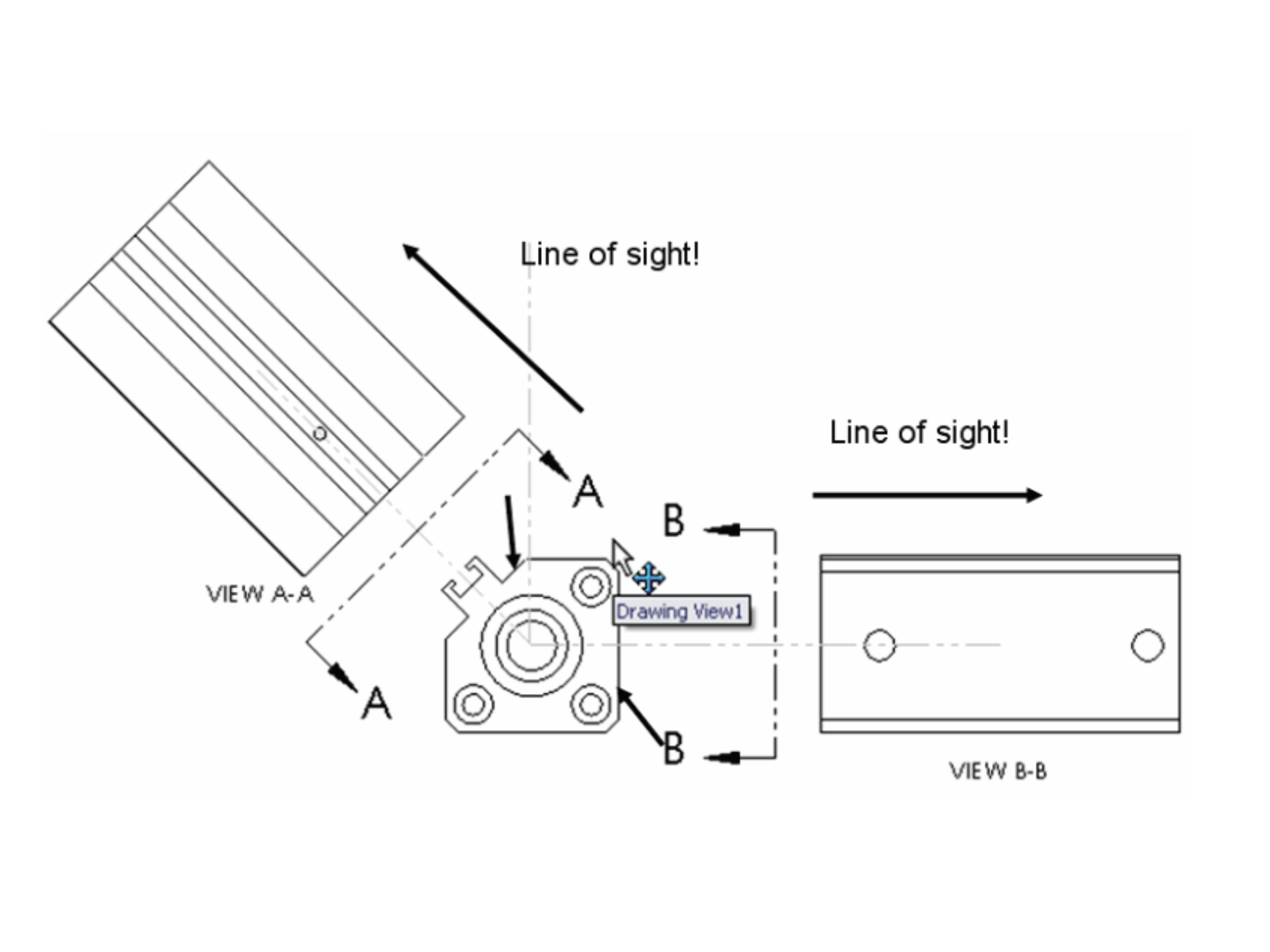
Cutting Plane Line
Shows imaginary cut. Arrows located at the end, direction indicates line of sight.
5 Most Important Lines
Visible Line
Hidden Line
Cutting Line
Centerline
Phantom Line
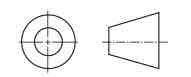
First Angle Projection
Back, left, bottom
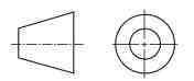
Third Angle Projection
Front, top, right (most commonly used).
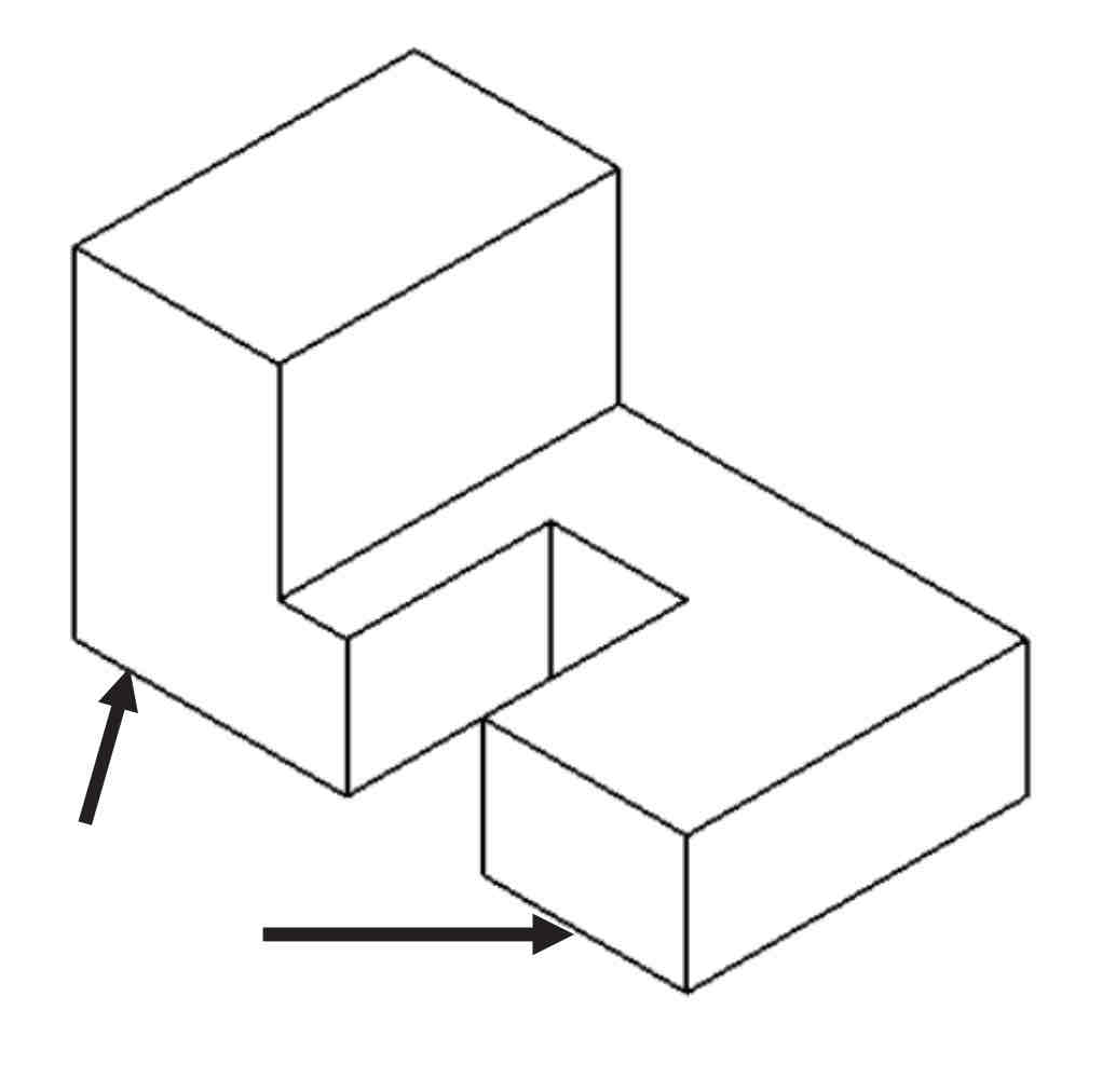
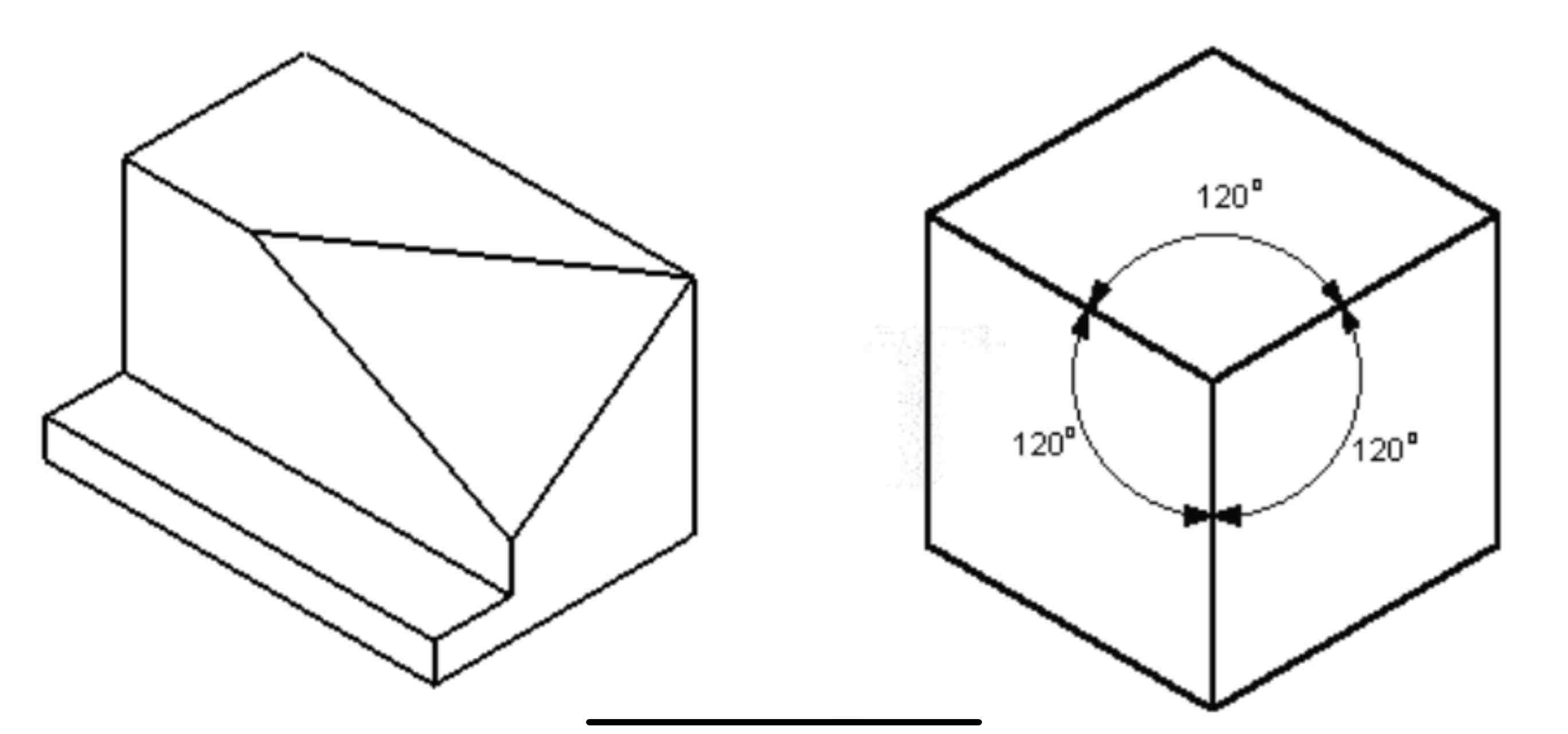
Isometric Projection
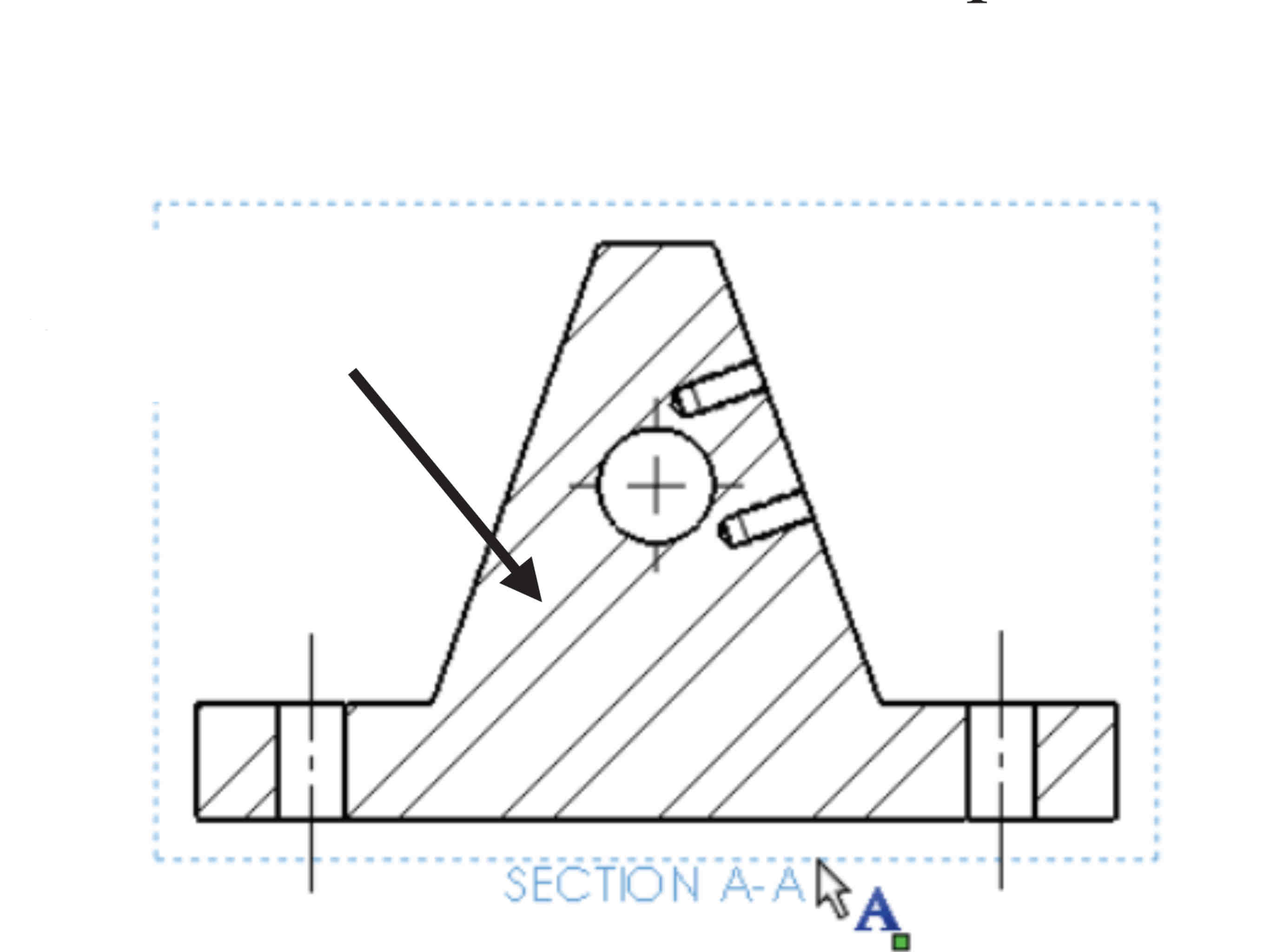
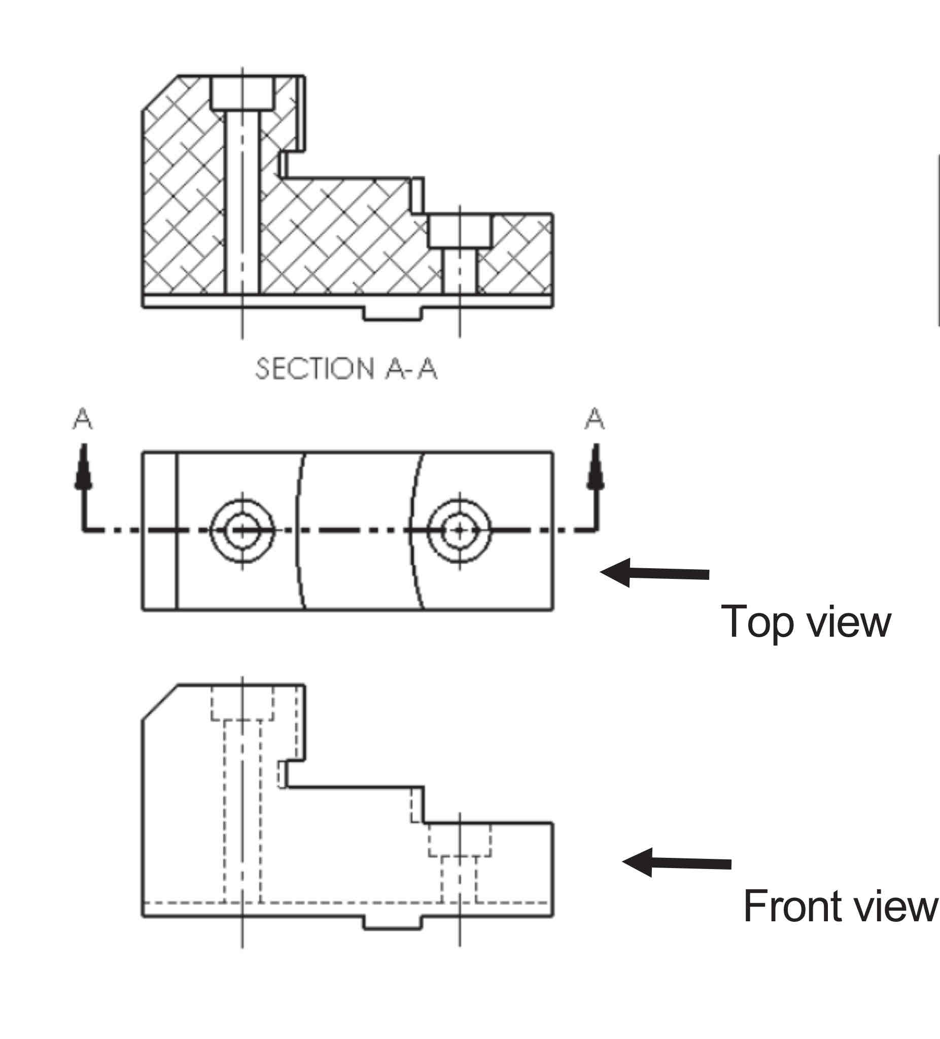
Section Views
Clarifies the interior part of an object that cannot clearly be seen with hidden lines.
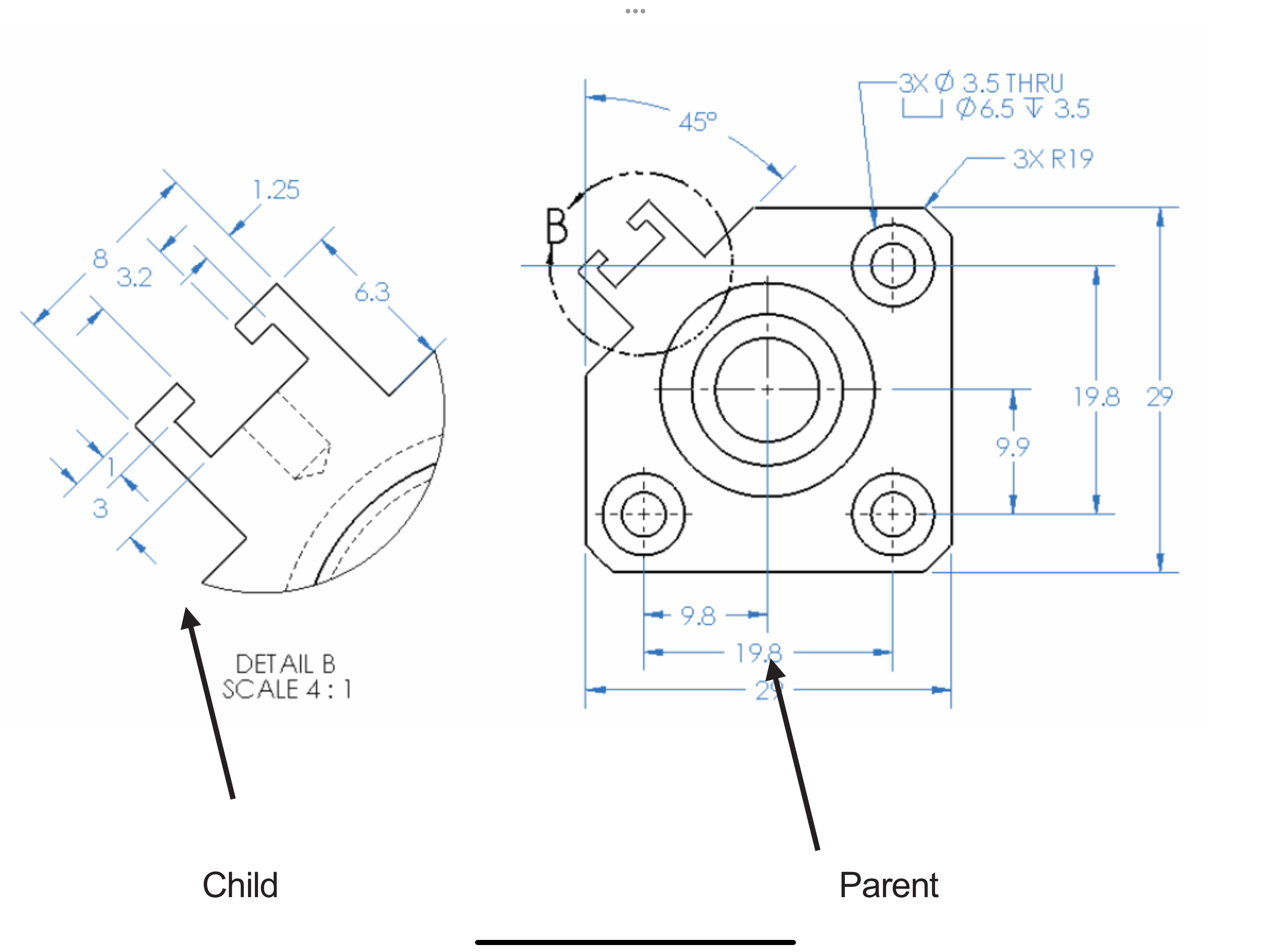
Detail View
Scales up a portion of a view to show details.
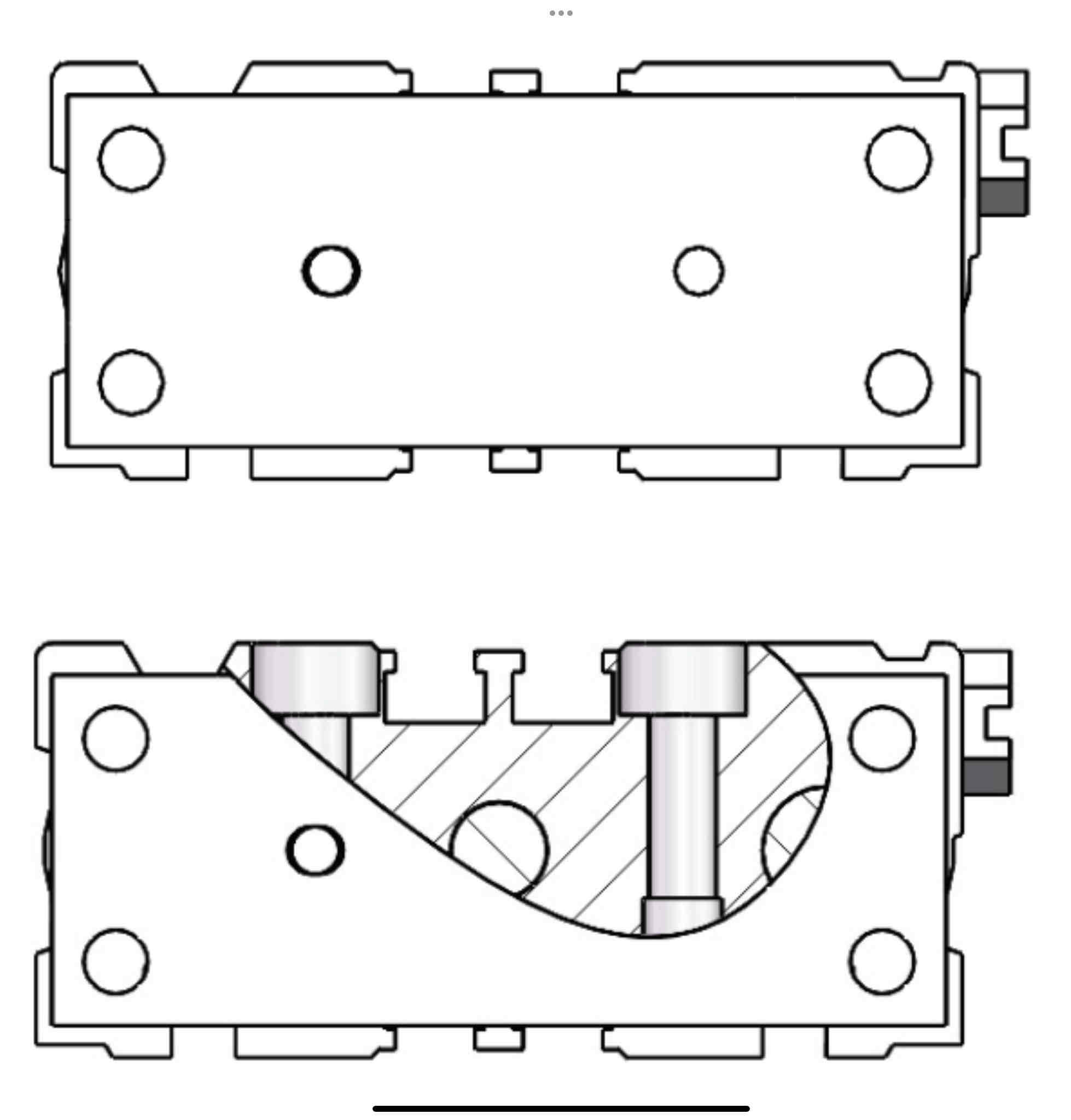
Broken-Out Section
Part of an existing drawing view, not a separate view.
Break Lines/Broken View
Allows the ability to add a break line to a selected view.
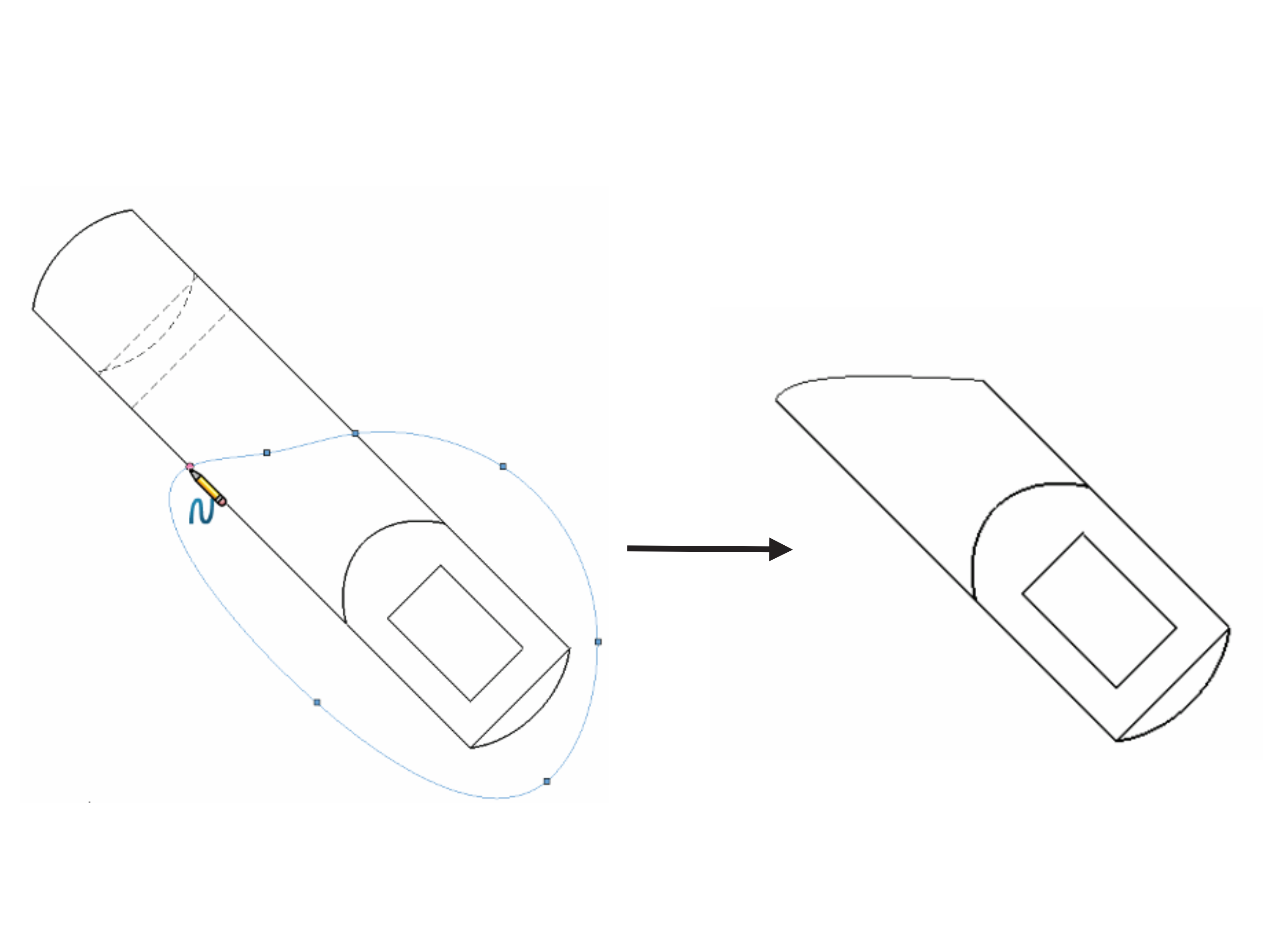
Crop View
The ability to crop an existing view at a 1:1 ratio.
Auxiliary View
Ability to display a plane parallel to an angle with true dimensions. Looks like oblique view.
Constructive Solid Geometry (CSG)
Describes the solid model as combinations of basic three dimensional shapes (aka primitives).
Boundary Representation (B-Rep)
Represents a solid as a collection of topology and geometry (surfaces, curves, and points). Uses equations.
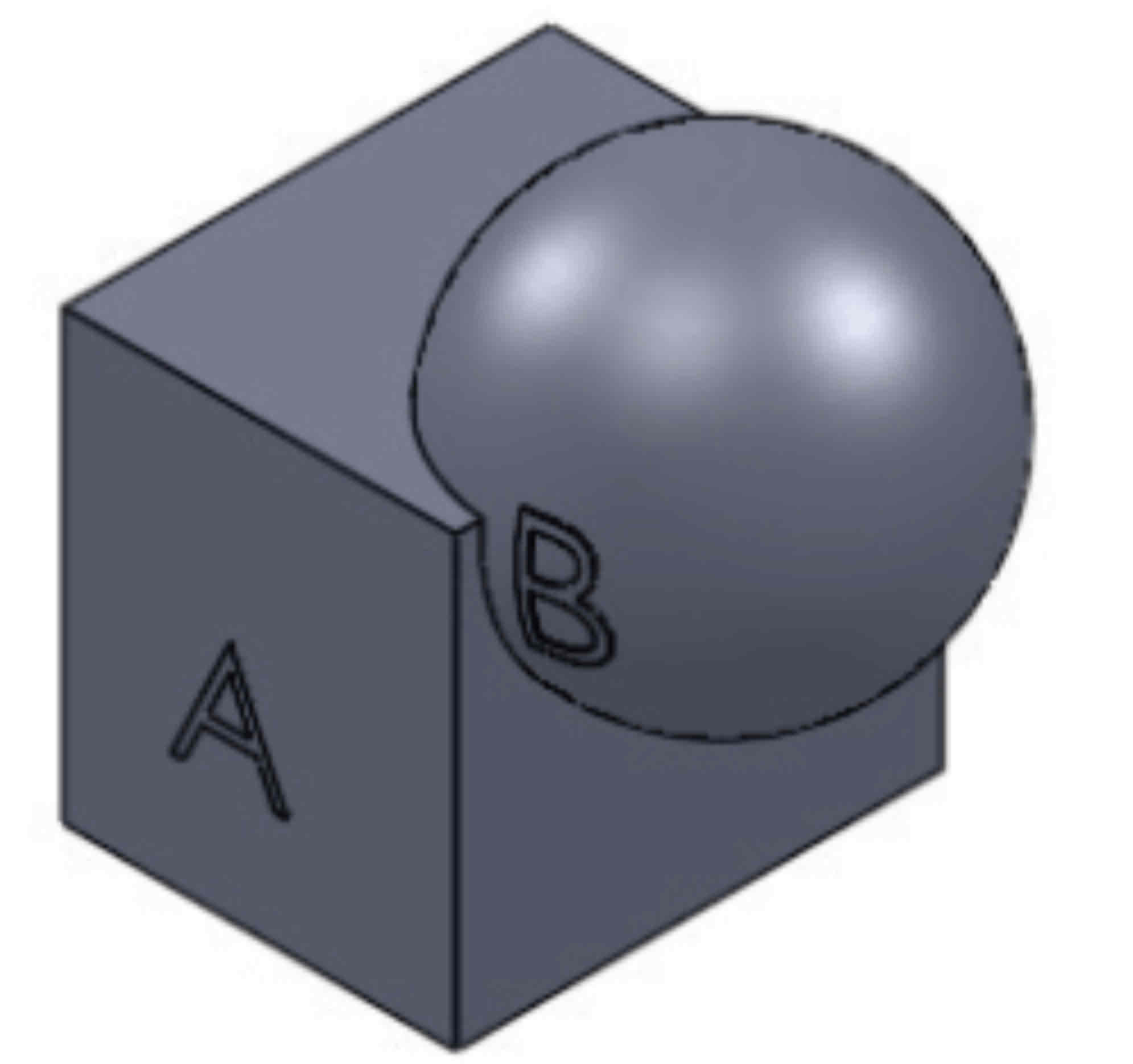
Boolean Union
The merger of 2 objects (A+B)
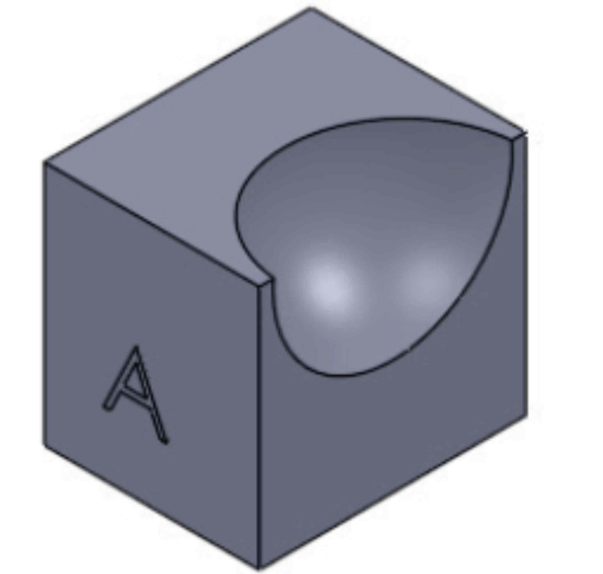
Boolean Difference
The subtraction of one object to another (A-B).
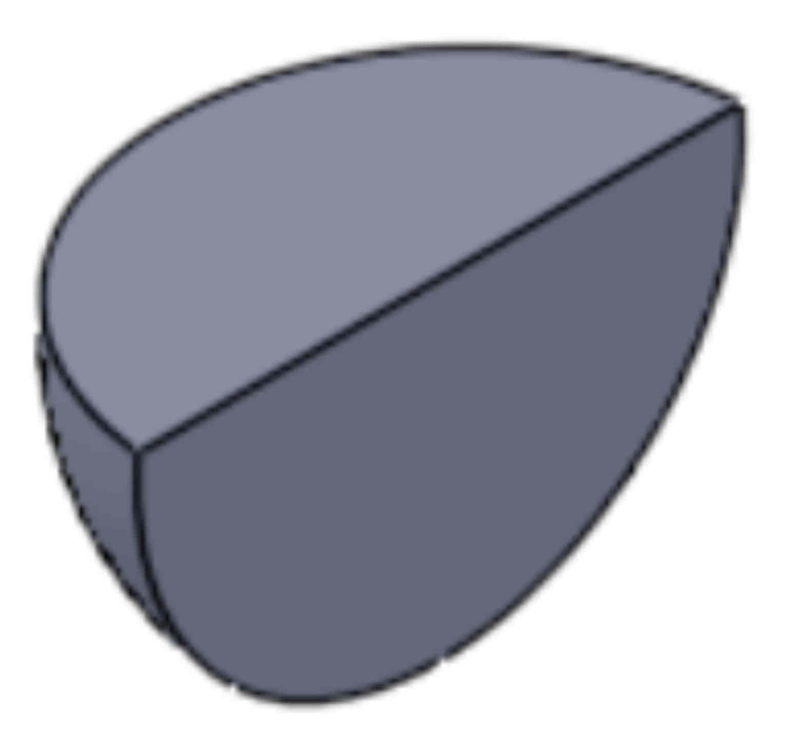
Boolean Intersection
The portion common to both objects (A ∩ B)
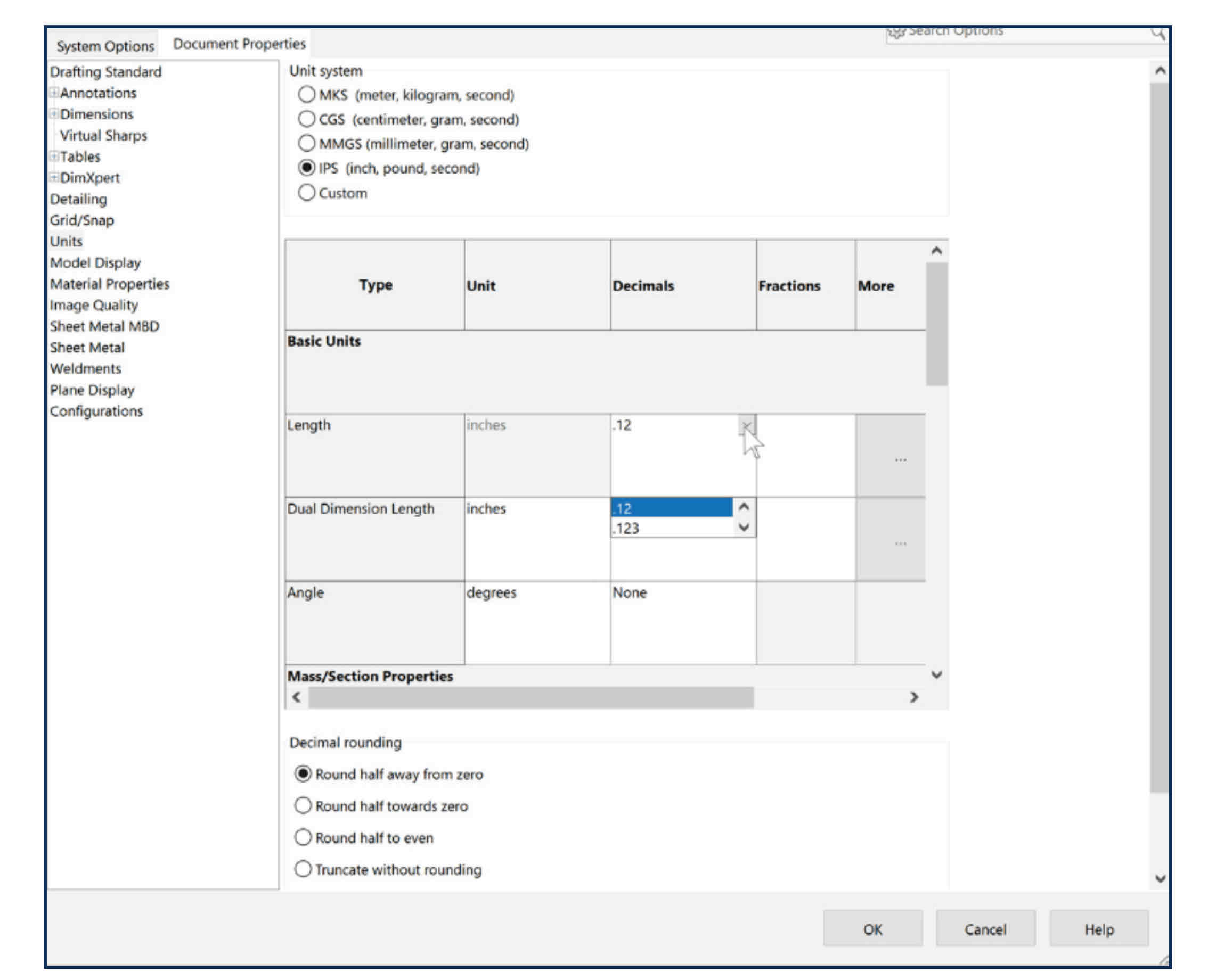
Precision
Number of decimal places.
Scale
drawing:actual
Datum
Our reference point
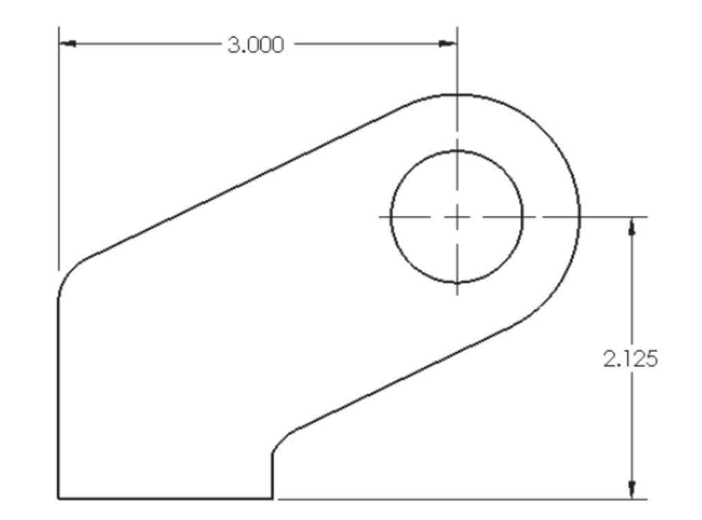
Location Dimension
Locates a vertical, horizontal, and center of hole position.
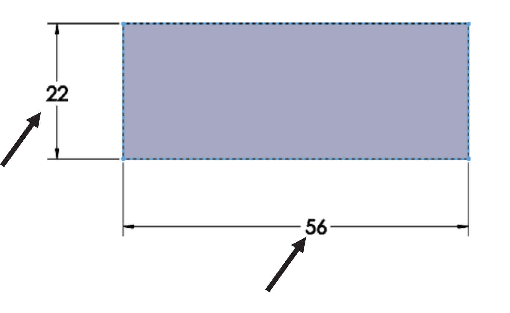
Size Dimentions
Every part has at least 3 dimensions.
Linear Dimension
Stagger Dimension
Aligned Dimension
Angular Dimension
A
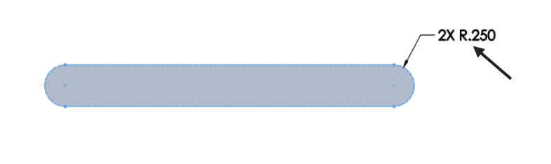
Arc Dimension
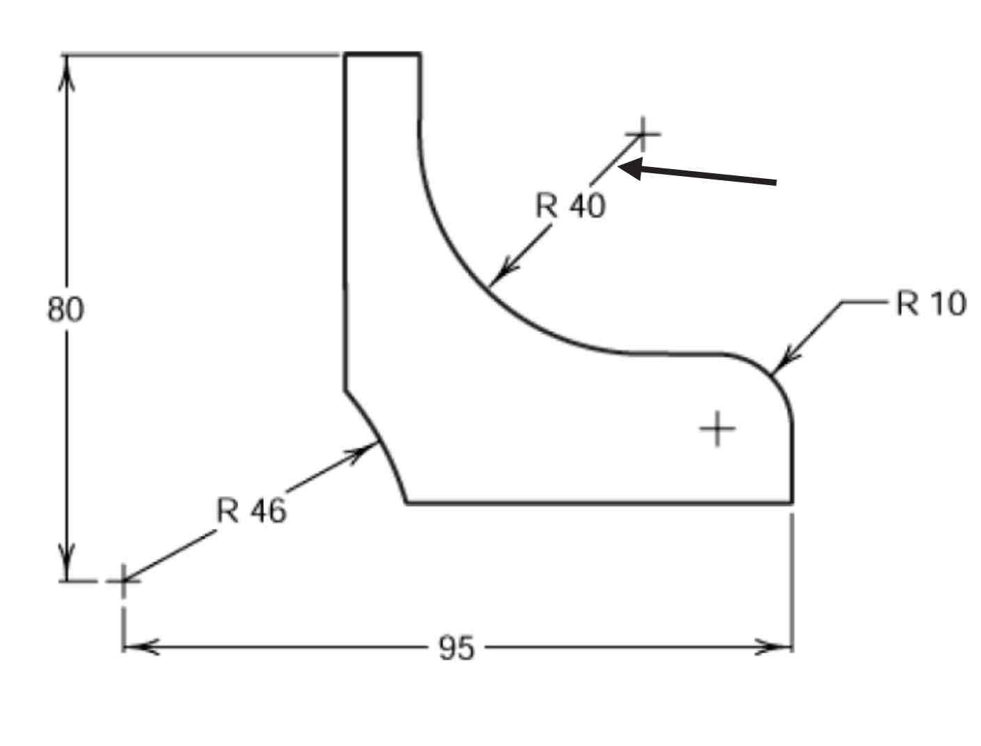
Radius Dimension
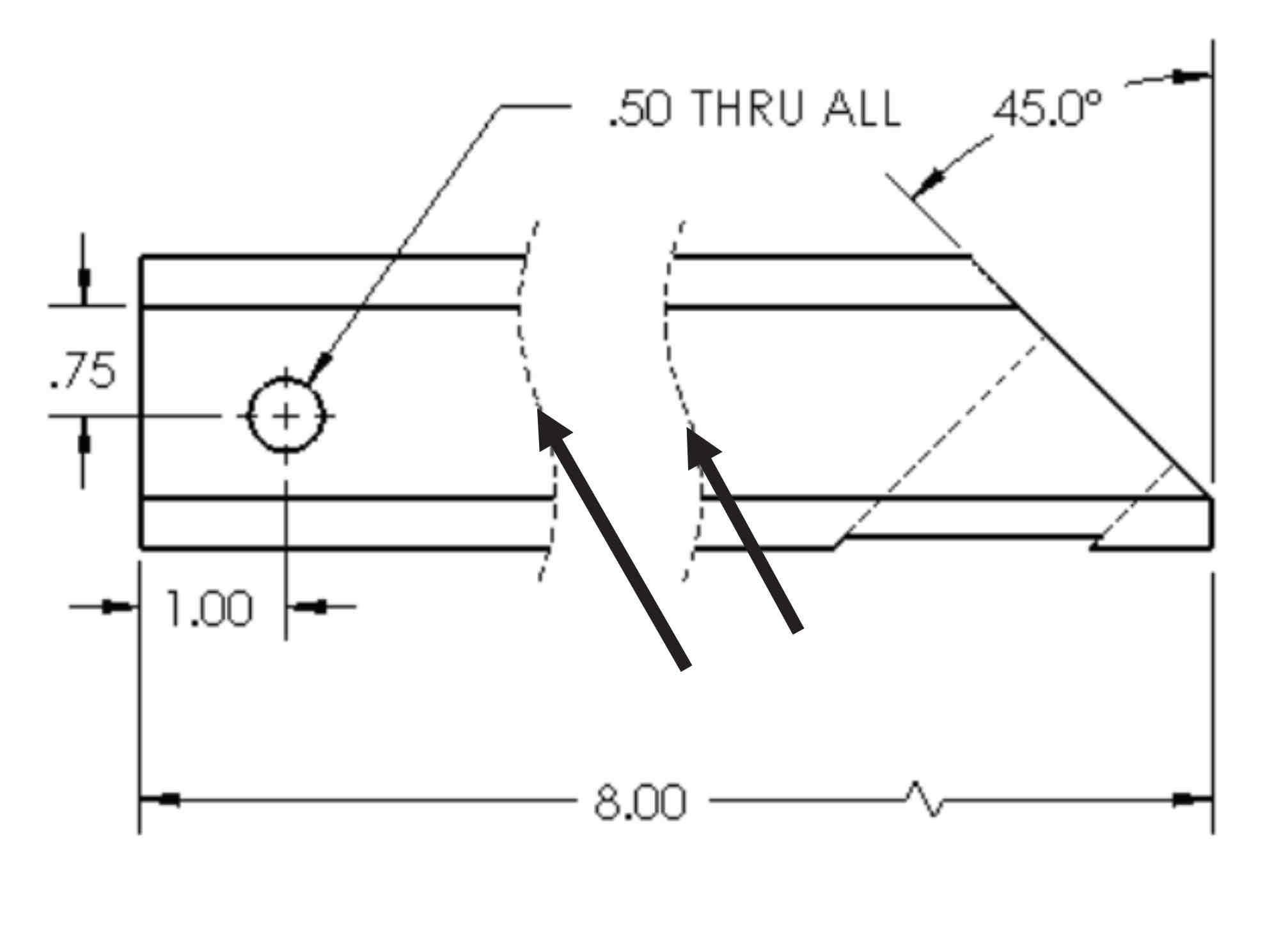
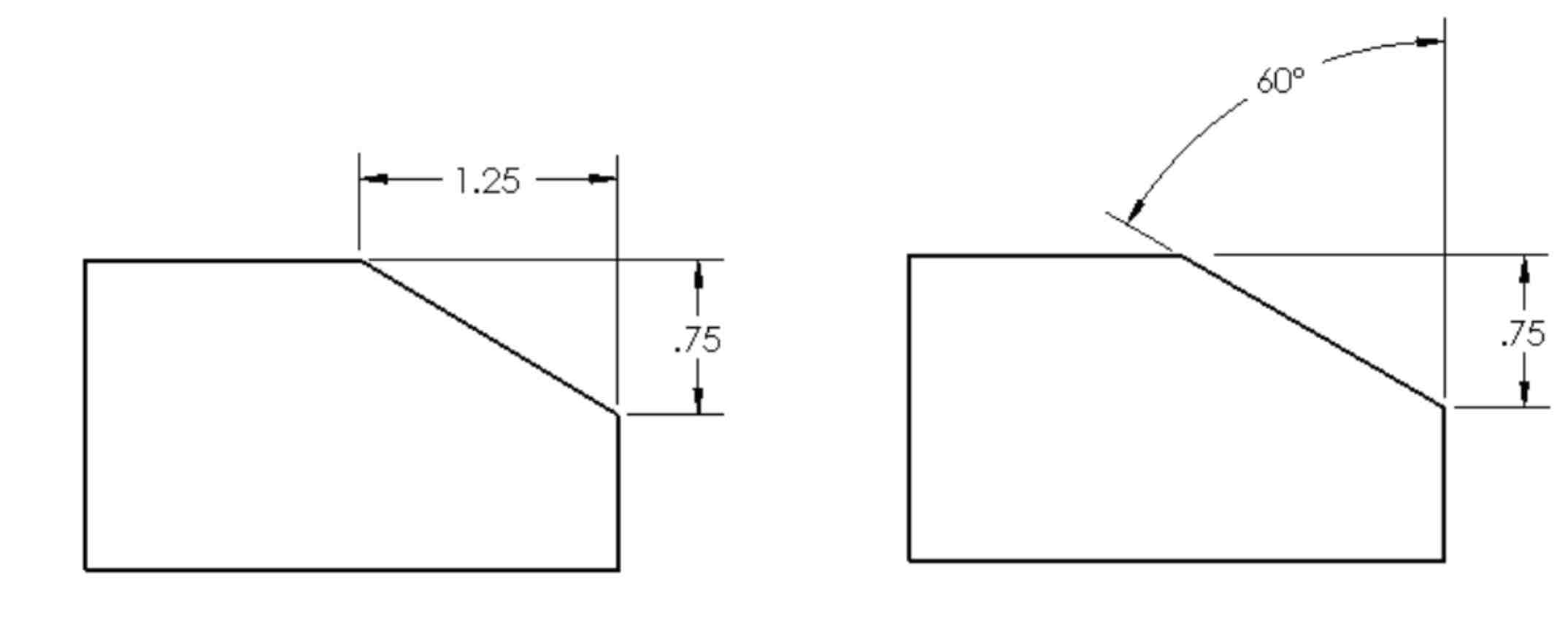
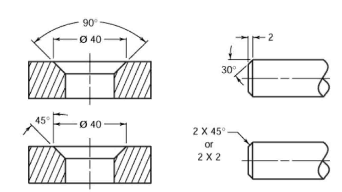
Chamfer Dimension
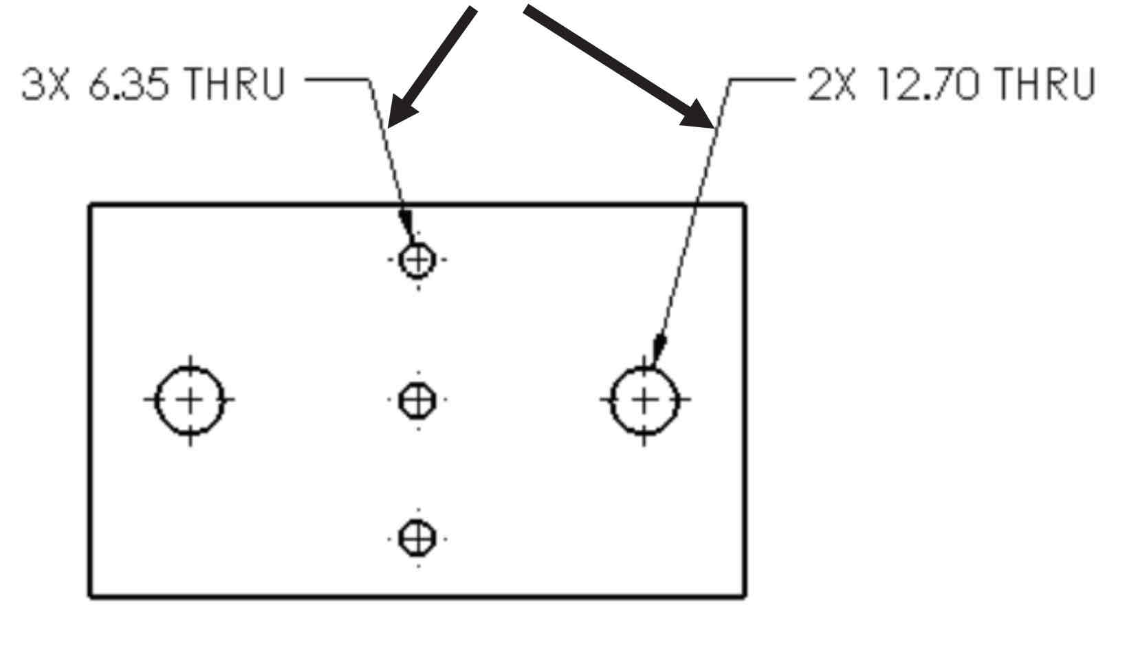
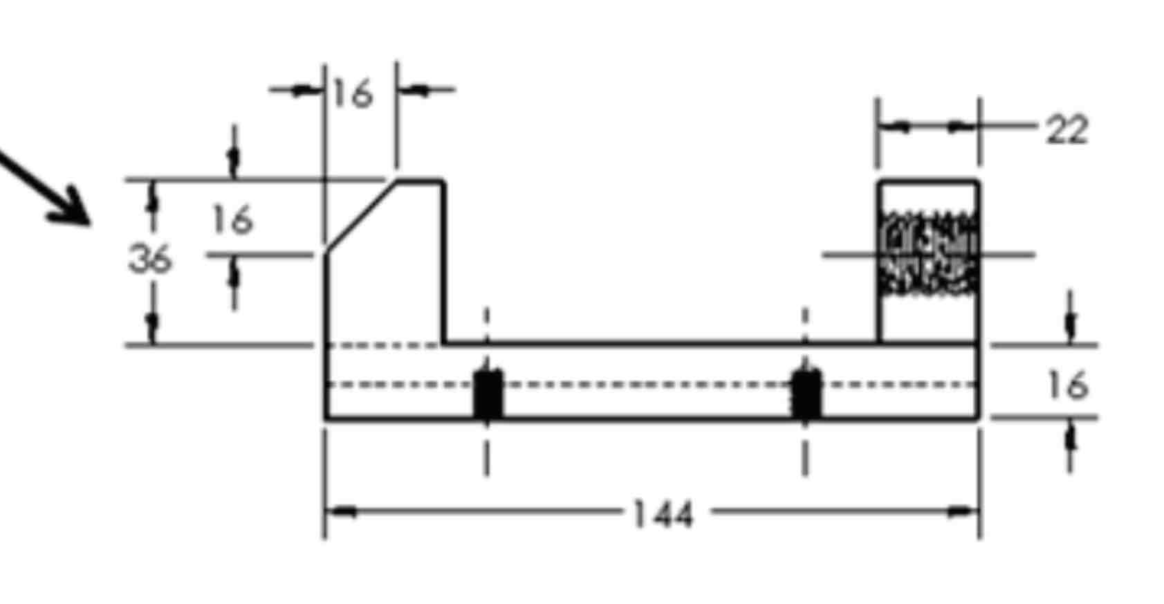
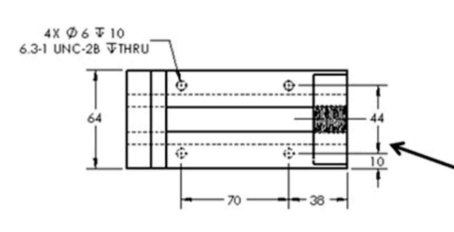
Fastener Hole Dimension
Tabular Dimensions
A table of dimensions.
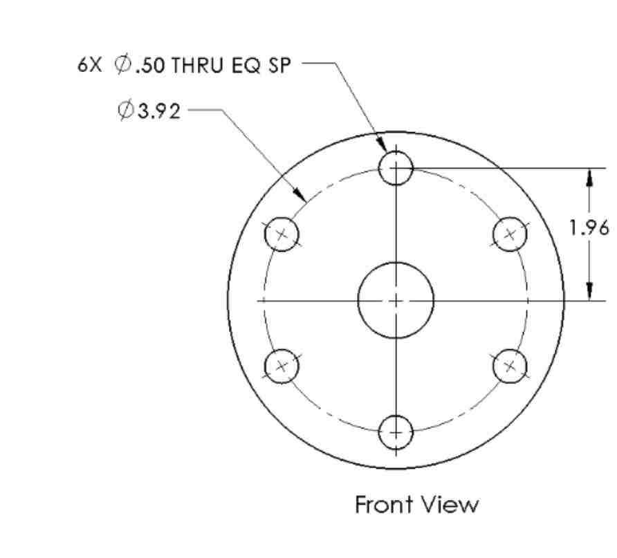
Equally Spaced on a Circle
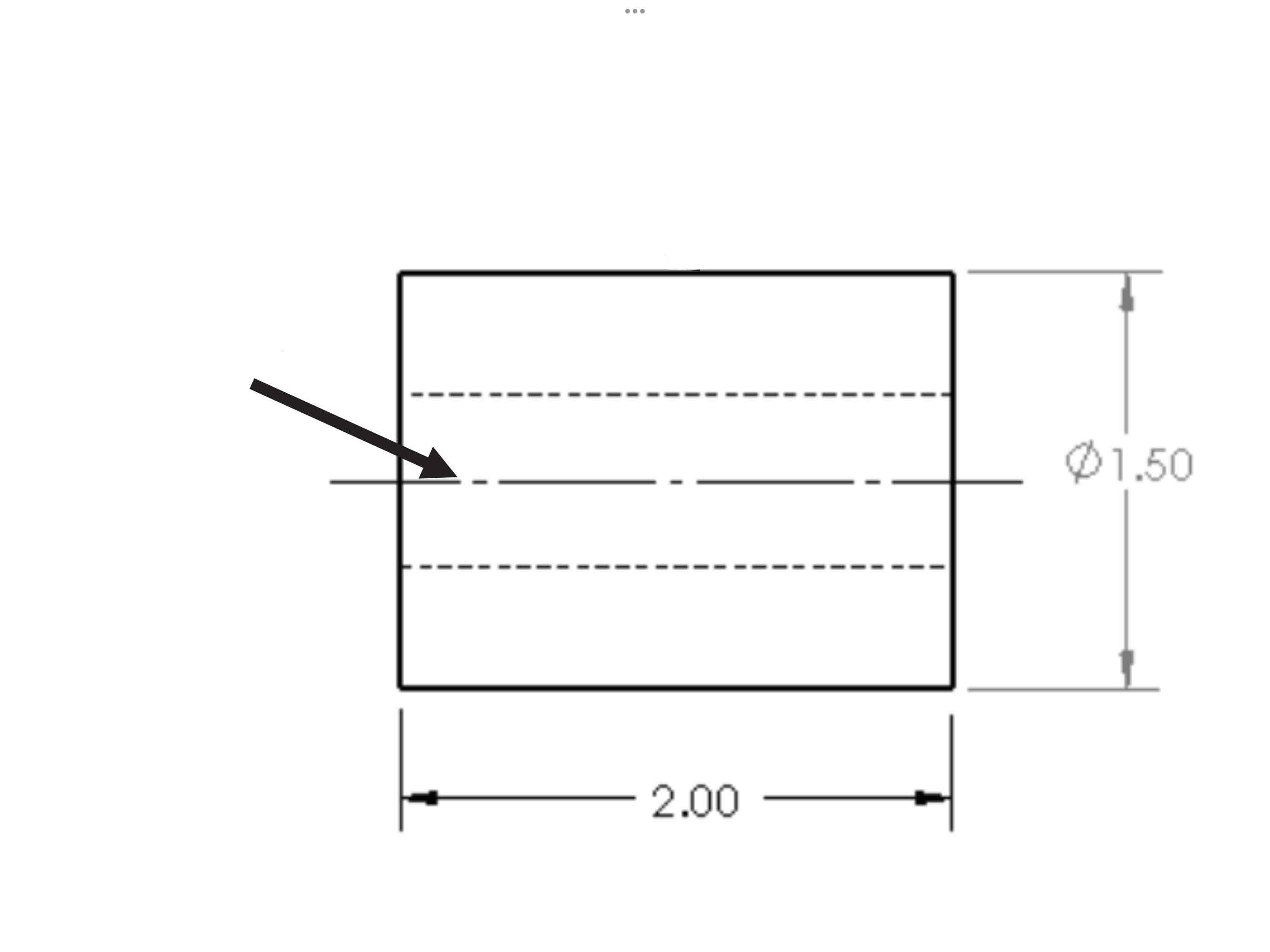
Point/center of a Circle Dimension
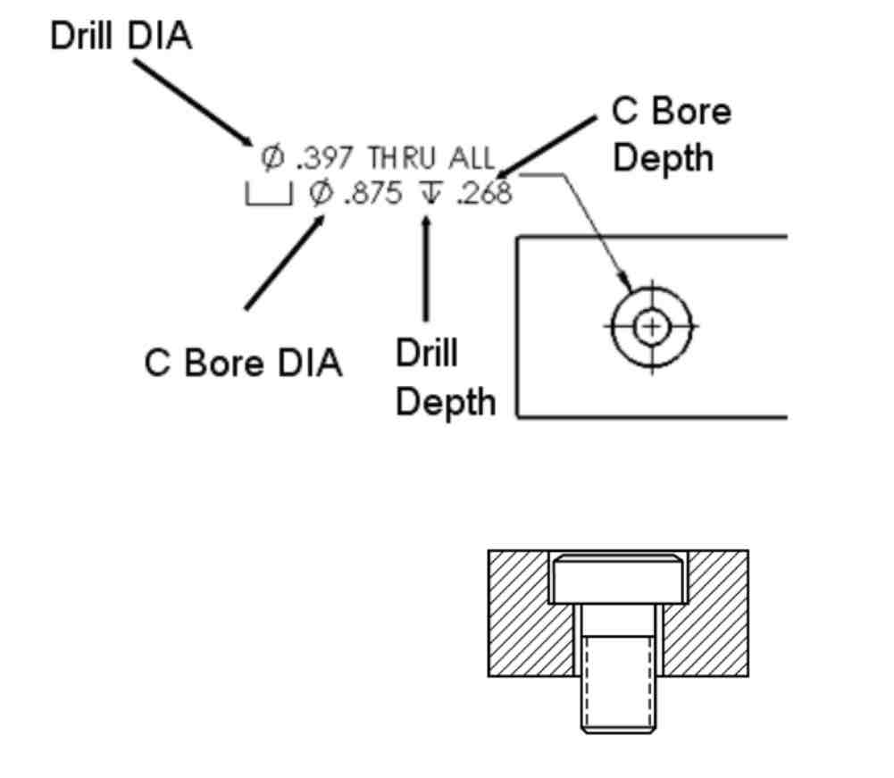
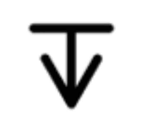
Counterbore
Countersink
Depth
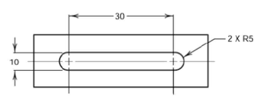
Slot Dimension
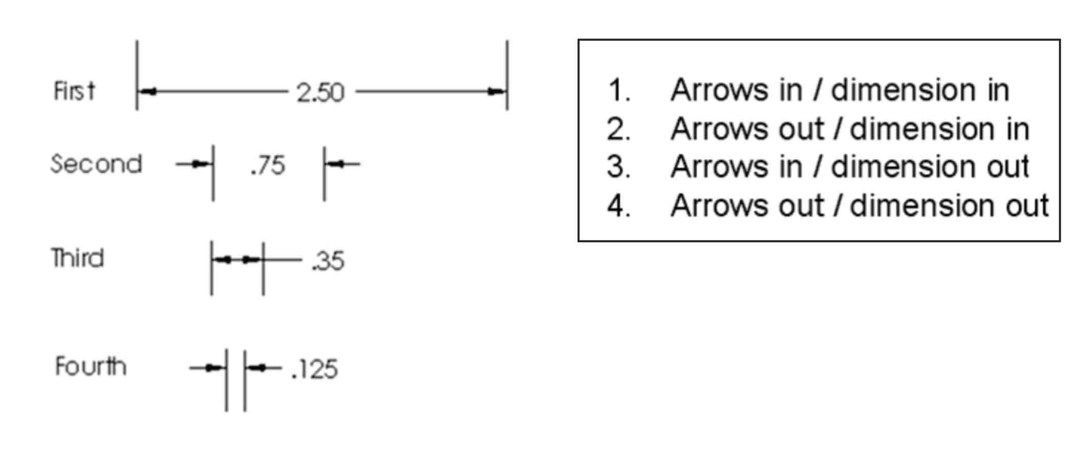
Order of Preference-Linear Dimension Lines
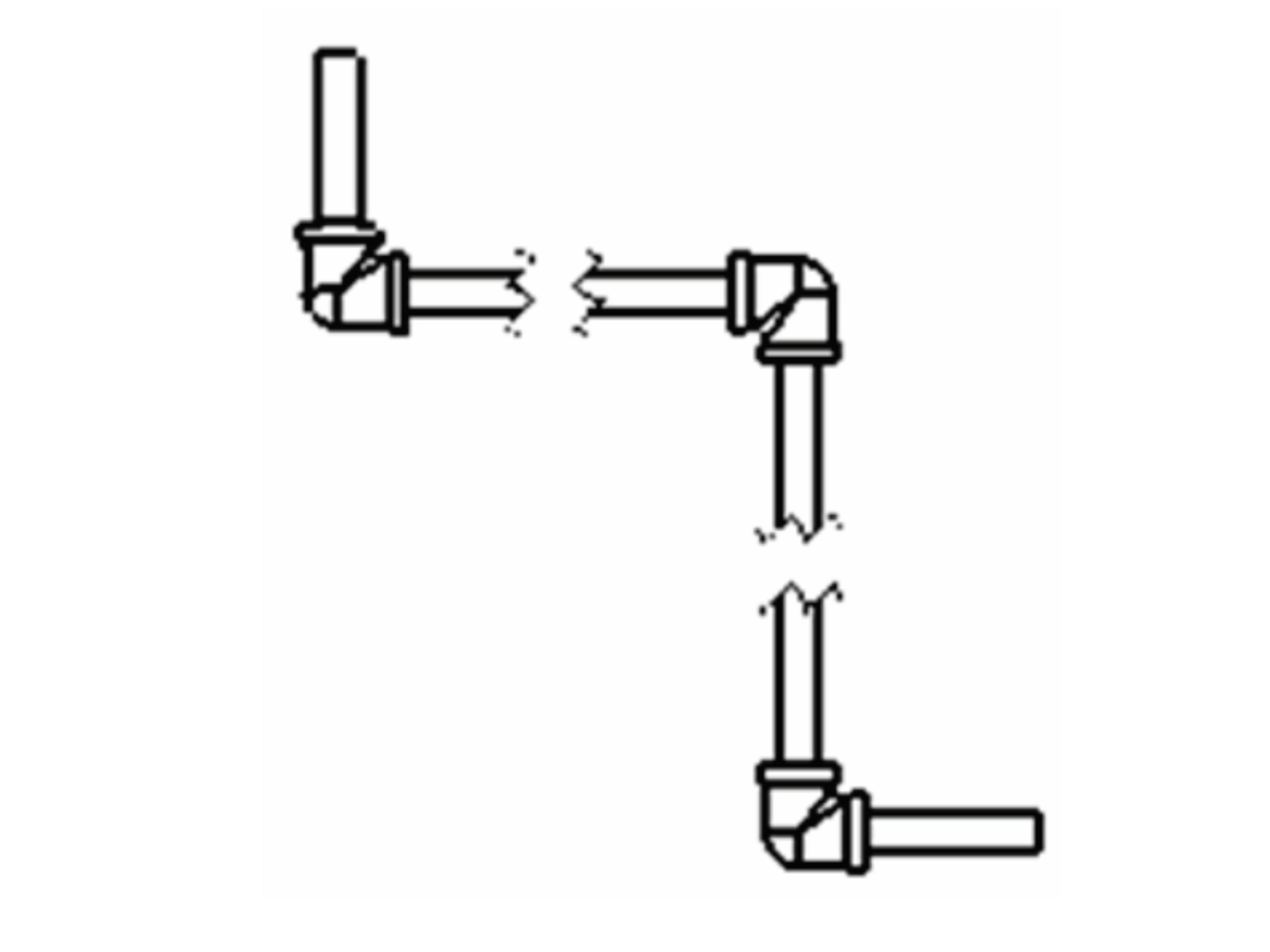
Relative Coordinates
Specifies a 3D location from a previous direction.
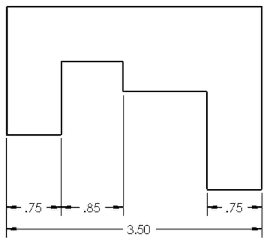
Continuous Dimensions
Steel
Cast Iron
Copper/Brass
Plastic
6061 Alloy
Rubber
Reference Dimensions